Compact energy-saving drying kiln

A drying kiln, compact technology, applied in the field of compact energy-saving drying kiln, can solve problems such as cracking, green body deformation, cross-sectional temperature difference, etc.

Pending Publication Date: 2017-09-05
DLT TECH CO LTD
View PDF7 Cites 2 Cited by
  • Summary
  • Abstract
  • Description
  • Claims
  • Application Information

AI Technical Summary

Problems solved by technology

Due to the one-sided air supply or dehumidification, it will also cause a cross-sectional temperature difference, causing deformation or cracking of the green body

Method used


Image

  • Compact energy-saving drying kiln
  • Compact energy-saving drying kiln
  • Compact energy-saving drying kiln

Examples


Embodiment Construction

[0027] In order to make the object, technical solution and advantages of the present invention clearer, the present invention will be further described in detail below in conjunction with the accompanying drawings. It is only stated here that the words for directions such as up, down, left, right, front, back, inside, outside, and side appearing or about to appear in the text of the present invention are only based on the accompanying drawings of the present invention, and they do not constitute a reference to the present invention. specific limitations.

[0028] An embodiment of the present invention provides a compact energy-saving drying kiln, including:

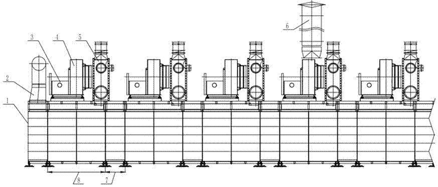
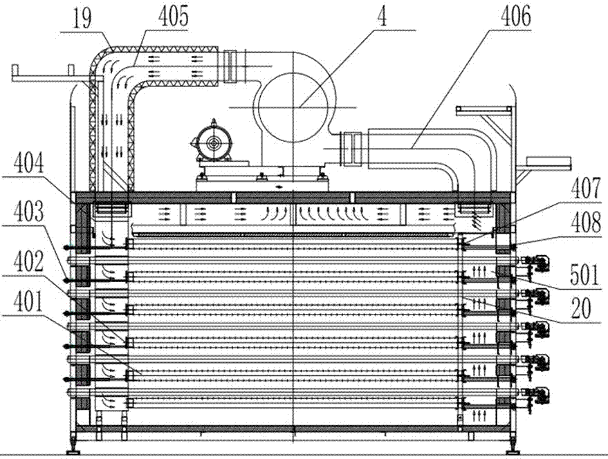
[0029] Such as figure 1 with figure 2 As shown, a standard kiln body composed of a short kiln section 7 and a long kiln section 8, the total length of the frame of the drying kiln 1 is composed of a plurality of standard kiln bodies. A heating fan 3 is installed on the top of each long kiln section 8 , the inlet of th...


PUM


Abstract

The invention discloses a compact energy-saving drying kiln. The drying kiln consists of multiple standard kiln bodies; vertical heat supply wind pipes and transverse wind blowing pipes are arranged in the standard kiln bodies; heat supply fans arranged on the standard kiln bodies are connected with the heat supply wind pipes; the heat supply wind pipes are connected with wind blowing pipes; hot wind is fed in the standard kiln bodies by the heat supply wind pipes and the wind blowing pipes; one ends of one set of wind blowing pipes are connected with the heat supply wind pipes on a driving side, and the other ends are fixed by first brackets; one ends of the other set of wind blowing pipes are connected with the heat supply wind pipes on a driven side, and the other ends are fixed by second brackets; detachable sealing plates are arranged at the ends of all the wind blowing pipes fixed by the first or second brackets; small pipe mouths are welded on the sealing plates; and square holes are formed in corresponding kiln walls, and are sealed by plugs. Pipe sections for extending out of the kiln are designed at one ends of all the wind blowing pipes, so that steel wire brushes can extend in from the pipes to clean dust, and compressed air pipes can extend in from the pipes to perform forced blowing so as to solve the blockage problem.

Description

technical field [0001] The invention relates to a compact energy-saving drying kiln, which is mainly used for drying the moisture of ceramic body. Background technique [0002] Ceramic production must go through a drying process to remove moisture in the green body and increase its strength to meet production and process needs. The multi-layer drying kiln has high efficiency and is generally welcomed by ceramic enterprises. Due to the small space of each layer and the dense air ducts, the traditional drying kiln does not have a dust removal port. However, the dust in the production workshops of ceramic tile enterprises is generally large. Some manufacturers directly use kiln flue gas for heating, and the blower pipe is easily blocked. When the air volume is insufficient to affect the drying efficiency or the body has defects, the kiln must be shut down. Then pull out the roller and manually process the cuts on the side wall, which not only causes production loss, but also h...

Claims


Application Information

Patent Timeline
IPC IPC(8): F26B15/02F26B21/00F26B23/10F26B21/08F26B25/08
CPCF26B15/02F26B21/001F26B21/08F26B23/10F26B25/08
Inventor 陶志坚程希如陈军郑旭东梁兴强
Owner DLT TECH CO LTD
Why Eureka
Try Eureka