Optical cable

An optical cable and cable core technology, applied in the field of information transmission equipment, can solve the problems that the protective layer does not have fire resistance, less wiring harnesses, and are easily damaged, so as to reduce the risk of being bitten by insects, improve transmission efficiency, and improve the effect of survival efficiency.

Inactive Publication Date: 2017-09-05
YANCHENG CHENGYANG ELECTRONICS TECH CO LTD
View PDF1 Cites 3 Cited by
  • Summary
  • Abstract
  • Description
  • Claims
  • Application Information

AI Technical Summary

Problems solved by technology

However, the outer protective layer of the optical cable in the prior art does not have fire resistance, so it is easily damaged when encountering a fire, and most of the optical cables in the prior art are laid in the wild, so it is easy to be damaged by small animals, especially Rats and other bites can easily cause damage to the optical cable
[0003] An optical cable introduced in the invention of "Optical Cable" (authorized announcement number: CN 202351474 U) has an aramid structure layer and a sheath structure layer outside the cable core composed of tightly wrapped optical fibers, and a sheath structure layer is provided with The stretch-resistant structure extending along the length of the cable, one of the disadvantages of this structure is that it can provide few wire bundles. When a large amount of data transmission is required, it cannot be transmitted in time, and it does not consider fire prevention, moisture resistance, insect bites and other disasters. The damage caused, so, in actual use, it takes a lot of energy to maintain

Method used


Image

  • Optical cable
  • Optical cable

Examples


Embodiment Construction

[0016] The following will clearly and completely describe the technical solutions in the embodiments of the present invention with reference to the accompanying drawings in the embodiments of the present invention. Obviously, the described embodiments are only some, not all, embodiments of the present invention. Based on the embodiments of the present invention, all other embodiments obtained by persons of ordinary skill in the art without making creative efforts belong to the protection scope of the present invention.

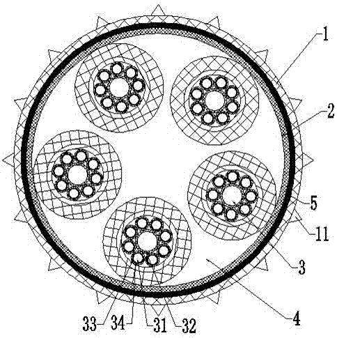
[0017] Such as figure 1 As shown, an optical cable of the present invention has the following structure: the isolation layer 2 is arranged inside the outer sheath 1, the cable core 3 is arranged in the chamber formed by the isolation layer 2, and the space between the isolation layer 2 and the cable core 3 is filled with The structure of the cotton yarn filler 4 and the cable core 3 is as follows: multiple bundles of optical fibers 31 are wound on a reinforcin...


PUM


Abstract

The invention discloses an optical cable. The isolation layer is arranged inside the outer sheath, and the cable core is arranged in the cavity formed by the isolation layer. Cotton yarn fillers are filled between the isolation layer and the cable core. The structure of the cable core is: multi-bundle The optical fiber is wound on a strength member, and the outer periphery of the optical fiber is wrapped with a sheath, which is made of glass yarn. Because no matter what the reason is for the optical fiber, there will be a certain amount of light refracted from the optical fiber. If the material wrapped around the optical fiber is a reflective material, it will affect the signal transmitted in the optical fiber. Therefore, a layer of light-absorbing material is provided inside the sheath. Layer, the light-absorbing material layer is made of glass fiber wool. The invention has the advantages that: the amount of data that can be transmitted will be greatly increased, which will help to improve the transmission efficiency of the data. The metal mesh is added in the outer sheath, and the anti-biting thorns are also added, which can reduce the risk of being bitten by insects, and can also reduce the risk of being bitten by insects. Increased fire prevention, waterproof measures, greatly improving the survival efficiency of optical cables.

Description

technical field [0001] The invention belongs to the technical field of information transmission equipment, and in particular relates to an optical cable. Background technique [0002] Optical cable is a very important part of optical communication system. It is widely used, small in outer diameter, light in weight, has certain flame retardant characteristics, moderate mechanical performance requirements and low cost, so it is often used between optical transmission modules in communication equipment The interconnection and interconnection between the communication equipment in the communication room. However, the outer protective layer of the optical cable in the prior art does not have fire resistance, so it is easily damaged when encountering a fire, and most of the optical cables in the prior art are laid in the wild, so it is easy to be damaged by small animals, especially Mice, etc. gnaw, which will easily cause damage to the optical cable. [0003] An optical cable i...

Claims


Application Information

Patent Timeline
Patent Type & Authority Applications(China)
IPC IPC(8): G02B6/44
CPCG02B6/443G02B6/4432
Inventor 吴琦杨光锦胡涵
Owner YANCHENG CHENGYANG ELECTRONICS TECH CO LTD
Why Eureka
Try Eureka