Digital phase-locked amplifier with multiple reference modes
A technology of digital phase-locking and reference mode, which is applied to the automatic control of power and electrical components, etc. It can solve the problems that the signal phase is meaningless and the lock-in amplifier does not give a solution, so as to achieve the effect of simplifying the design
- Summary
- Abstract
- Description
- Claims
- Application Information
AI Technical Summary
Problems solved by technology
Method used
Image
Examples
Embodiment 1
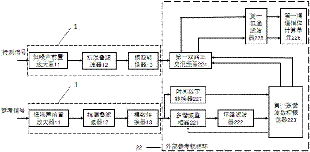
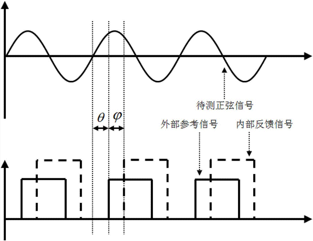
[0080] Such as figure 2 with image 3 As shown, this embodiment adopts the external reference mode, and its working principle is as attached image 3 As shown, the phase difference between the sinusoidal signal to be measured and the external reference signal is θ—that is, the phase value of the signal to be measured. In this mode, the analog link 1 has two channels, one of which is used to input the signal to be tested, and the other is used to input the reference signal.
[0081] In the external reference mode, that is, the phase difference between the sinusoidal signal to be measured and the external reference signal is θ—that is, the phase value of the signal to be measured.
[0082] Specifically, the external reference phase-locked loop 22 includes a sequentially connected multi-harmonic phase detector 221, a loop filter 222, a first multi-harmonic numerically controlled oscillator 223, and a first dual-way quadrature mixer 224 , the first low-pass filter 225 and the ...
Embodiment 2
[0106] In this embodiment, the reference phase-locked loop is a cross-reference phase-locked loop mode, and the cross-reference mode is for the measurement that does not provide a standard reference signal, or only needs to measure the phase difference between two channels of signals to be measured. The cross-reference mode includes two types: the known frequency of the signal to be tested and the frequency of the unknown signal to be tested. The working mode of the known frequency of the signal to be tested is included in the frequency of the unknown signal to be tested, so the following is only for the case of unknown frequency of the signal to be tested. describe.
[0107] The cross-reference mode has basically the same processing for the two input channels, one of which is called the reference channel as a reference point; the other is called the main channel, and its phase value is relative to the signal of the reference channel. The working process is as follows and attac...
Embodiment 3
[0155] The present embodiment is an internal reference mode, that is, the reference phase-locked loop is an internal reference phase-locked loop 24, and there are two working modes in it: 1, a single channel signal to be measured without a reference signal, and the signal frequency is unknown; 2, a lock-in amplifier A drive signal is provided for the circuit to be tested, and the frequency of the signal to be tested is known.
[0156] For the first working mode of the internal reference mode, it is similar to the single-channel cross-reference mode, as shown in the attached Figure 5 shown. Specifically, the internal reference phase-locked loop 24 includes a second frequency extractor 241, a third multi-harmonic numerically controlled oscillator 242, a third dual-way quadrature mixer 243, and a third low-pass filter connected in sequence. 244 and a third amplitude and phase calculation unit 245; where the signal to be measured is converted into two digital signals to be measu...
PUM
 Abstract
Description
Claims
Application Information
 - R&D
- Intellectual Property
- Life Sciences
- Materials
- Tech Scout
- Unparalleled Data Quality
- Higher Quality Content
- 60% Fewer Hallucinations
Browse by: Latest US Patents, China's latest patents, Technical Efficacy Thesaurus, Application Domain, Technology Topic, Popular Technical Reports.
© 2025 PatSnap. All rights reserved.Legal|Privacy policy|Modern Slavery Act Transparency Statement|Sitemap|About US| Contact US: help@patsnap.com


