Intelligent tube push bench cutterhead

A technology of pipe jacking and machine tool, used in mining equipment, earth-moving, tunnels, etc., can solve the problems of tool damage, maximum drilling depth, whether difficult tools can be reached, etc., to prevent tool damage, easy peeling and excavation. , Guarantee the effect of service life

Active Publication Date: 2017-09-08
上海矩顶工程科技有限公司
View PDF8 Cites 0 Cited by
  • Summary
  • Abstract
  • Description
  • Claims
  • Application Information

AI Technical Summary

Problems solved by technology

[0004] In order to solve the problem that the existing jacking machine is difficult to find out whether the cutter has reached the maximum drilling depth in time and is likely to cause damage to the cutter, the purpose of the present invention is to provide an intelligent pipe jacking machine cutter head

Method used


Image

  • Intelligent tube push bench cutterhead
  • Intelligent tube push bench cutterhead

Examples


Embodiment 1

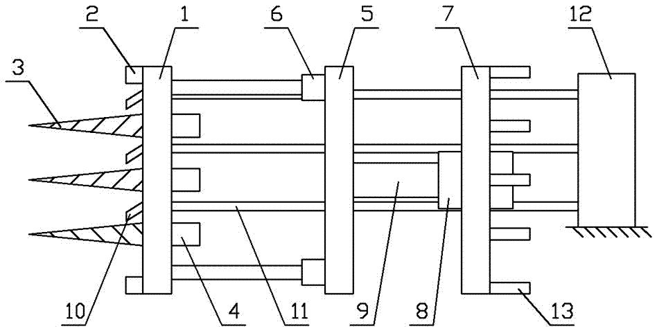
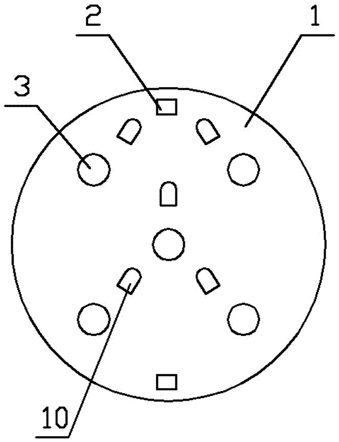
[0025] Such as figure 1 and figure 2 As shown, it includes a jacking disc 1, a central controller and an alarm; the jacking disc 1 is circular; along the jacking direction, a pressure sensor 2 and evenly distributed drill bits 3 are arranged on the front end of the jacking disc 1, and the jacking disc 1 The first motor 4 is fixed on the rear end surface of the tray 1, and the drill 3 is connected to the power output shaft of the first motor 4; the central axis of the drill 3 is placed horizontally; the pressure sensor 2, the first motor 4, and the alarm are connected to the central The controllers are connected by electrical signals.

[0026] Along the jacking direction, a circular positioning plate 5 is provided behind the jacking plate 1; the positioning plate 5 is the same size as the jacking plate 1, and the center of the circle is aligned; the front end of the positioning plate 5 is provided with a horizontal electro-hydraulic rod 6, The top of the rod 6 is fixedly con...

Embodiment 2

[0032] Such as figure 1 and figure 2 As shown, it includes a jacking disc 1, a central controller and an alarm; the jacking disc 1 is circular; along the jacking direction, a pressure sensor 2 and evenly distributed drill bits 3 are arranged on the front end of the jacking disc 1, and the jacking disc 1 The first motor 4 is fixed on the rear end surface of the tray 1, and the drill 3 is connected to the power output shaft of the first motor 4; the central axis of the drill 3 is placed horizontally; the pressure sensor 2, the first motor 4, and the alarm are connected to the central The controllers are connected by electrical signals.

[0033] Along the jacking direction, a circular positioning plate 5 is provided behind the jacking plate 1; the positioning plate 5 is the same size as the jacking plate 1, and the center of the circle is aligned; the front end of the positioning plate 5 is provided with a horizontal electro-hydraulic rod 6, The top of the rod 6 is fixedly con...

Embodiment 3

[0038] Such as figure 1 and figure 2 As shown, it includes a jacking disc 1, a central controller and an alarm; the jacking disc 1 is circular; along the jacking direction, a pressure sensor 2 and evenly distributed drill bits 3 are arranged on the front end of the jacking disc 1, and the jacking disc 1 The first motor 4 is fixed on the rear end surface of the tray 1, and the drill 3 is connected to the power output shaft of the first motor 4; the central axis of the drill 3 is placed horizontally; the pressure sensor 2, the first motor 4, and the alarm are connected to the central The controllers are connected by electrical signals.

[0039] Along the jacking direction, a circular positioning plate 5 is provided behind the jacking plate 1; the positioning plate 5 is the same size as the jacking plate 1, and the center of the circle is aligned; the front end of the positioning plate 5 is provided with a horizontal electro-hydraulic rod 6, The top of the rod 6 is fixedly con...


PUM


Abstract

The invention discloses an intelligent tube push bench cutterhead which comprises a jacking-in disk, a central controller and an alarm, wherein the jacking-in disk is round; along the jacking-in direction, a pressure sensor and uniformly distributed drills are disposed on the front end face of the jacking-in disk, a first motor is fixed on the rear end face of the jacking-in disk, and the drills are connected to a power output shaft of the first motor; center shafts of the drills are placed horizontally; and the pressure sensor, first motor and alarm are connected to the central controller by electric signals. The intelligent tube push bench cutterhead disclosed by the invention has the beneficial effects that whether the drills reach a maximum drilling depth can be detected automatically in time; cutter damage can be prevented; retraction and jacking-in actions of cutters can be controlled automatically; a lot of manual workloads are saved; the cutters are automatically controlled to deflect at multiple angles and then start drilling into rock soil; soil drilling effects are better; and the rock soil can be stripped and excavated more easily.

Description

technical field [0001] The invention belongs to the technical field of pipe jacking engineering equipment, and in particular relates to an intelligent pipe jacking machine cutter head. Background technique [0002] With the development of urban economy and the expansion of city scale, there are more and more constructions of various municipal projects such as subways, cross-river tunnels, and sewage pipelines. As a non-excavation construction method for laying underground pipelines, the pipe jacking construction method has little impact on the surrounding environment and relatively low cost, so it has been widely used. During the pipe jacking construction process, the concrete pipe is pushed through the soil layer by means of the jacking force from the oil cylinder or jack, and the subsequent pipe is buried. Its greatest advantage lies in the use of underground excavation without slotting way, thereby avoiding the direct impact on the buildings or structures on the ground. ...

Claims


Application Information

Patent Timeline
Patent Type & Authority Applications(China)
IPC IPC(8): E21D9/10E21D9/00
CPCE21D9/003E21D9/1006Y02P70/10
Inventor 沈传雄
Owner 上海矩顶工程科技有限公司
Why Eureka
Try Eureka