Power generation mechanism
A generator and power generation technology, applied in hydropower, engine components, machines/engines, etc., can solve problems such as energy loss, machine damage, and water turbines cannot perform effective energy rotation, so as to avoid energy loss, reduce vibration, and avoid Effect of reduced energy conversion rate
- Summary
- Abstract
- Description
- Claims
- Application Information
AI Technical Summary
Problems solved by technology
Method used
Image

Examples
Embodiment 1
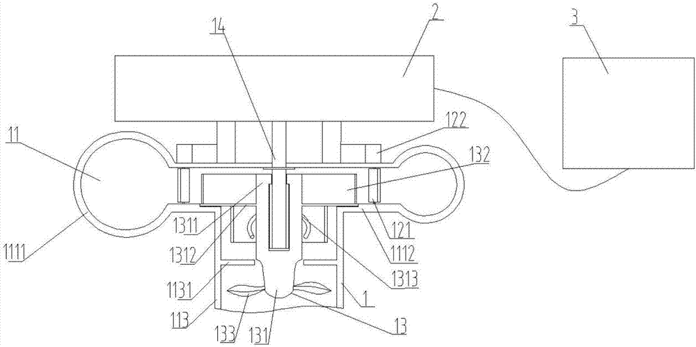
[0027] The invention relates to a power generating mechanism, the structure diagram of which is as follows figure 1 and figure 2 As shown, it includes a water wheel assembly 1, a generator 2, and a storage battery 3. The water wheel assembly 1 is connected to the generator 2, and the generator 2 generates electricity through the movement of the water wheel assembly 1. The storage battery 3 and the generator 2 are connected by wires, and the storage battery 3 is used for storing the electricity generated by the generator 2 .
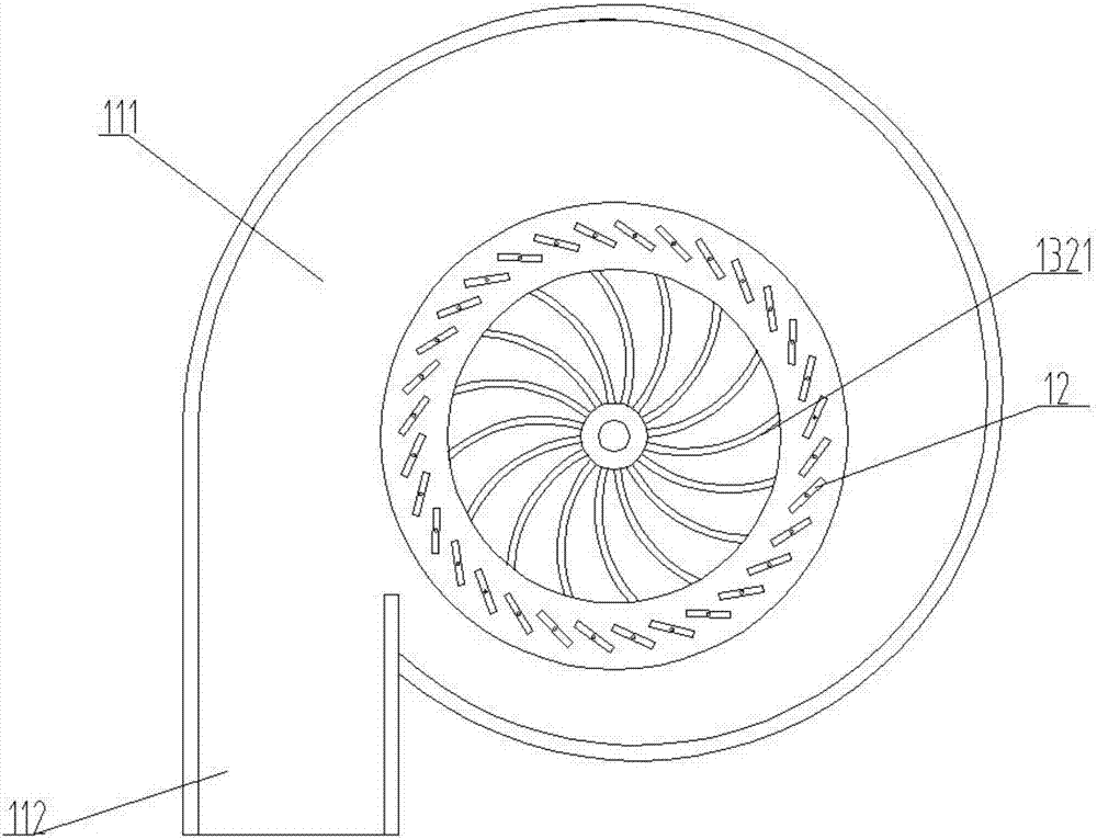
[0028] The water wheel assembly 1 includes a casing 11, a flow guiding device 12, a water wheel device 13, and a rotating shaft 14, and the flow guiding device 12, the water wheel device 13, and the rotating shaft 14 are arranged inside the casing 11 .
[0029] The casing 11 includes a volute waterway 111, a water inlet 112 and an outlet waterway 113, the volute waterway 111 includes a hollow pipe 1111 and a sealing plate 1112, the water inlet 112 is c...
Embodiment 2
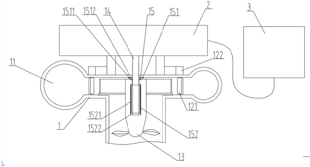
[0042] image 3 It is a preferred structural diagram of the power generating mechanism of the present invention; the water wheel assembly 1 also includes a permanent magnet assembly 15, and the permanent magnet assembly 15 includes a first permanent magnet group 151 and a second permanent magnet group 152, the first The permanent magnet group 151 includes a first ring body 1511 and a second ring body 1512, the first ring body 1511 and the second ring body 1512 are permanent magnets, and the first ring body 1511 is arranged on the rod body 1311 On the surface, the second ring body 1512 is arranged on the rotating shaft 14, and the second ring body 1512 is preferably arranged at a position corresponding to the first ring body 1511, and the second ring body 1512 and the first ring body 1512 are A ring body 1511 magnetically attracts each other along the vertical direction;
[0043] The second permanent magnet group 152 includes several first magnet blocks 1521 and several second...
Embodiment 3
[0047] Such as Figure 4 as shown, Figure 4 It is a preferred structural diagram of the power generating mechanism of the present invention, which is improved on the basis of Embodiment 1 and Embodiment 2, specifically, the combination of Embodiment 1 and Embodiment 2 is improved.
[0048] The specific working process of the power generating mechanism is as follows: when the water flow enters the volute water channel 111 from the water inlet channel 112, the water flow passes through the deflector 121 and impacts the arc-shaped piece 1321, and the control device 122 Adjusting the deflector 121 changes the angle at which the water flow impacts the arc-shaped piece 1321, so that the water flow pushes the water wheel device 13 to rotate, and the structure of the volute water channel 111 adjusts the water flow due to the The different water pressures caused by the different flow distances in the volute water channel 111 alleviate the deflection of the water wheel device 13 cause...
PUM
 Abstract
Description
Claims
Application Information
 - R&D
- Intellectual Property
- Life Sciences
- Materials
- Tech Scout
- Unparalleled Data Quality
- Higher Quality Content
- 60% Fewer Hallucinations
Browse by: Latest US Patents, China's latest patents, Technical Efficacy Thesaurus, Application Domain, Technology Topic, Popular Technical Reports.
© 2025 PatSnap. All rights reserved.Legal|Privacy policy|Modern Slavery Act Transparency Statement|Sitemap|About US| Contact US: help@patsnap.com