Permanent magnetic motor gullet torque measuring method

A technology of cogging torque and permanent magnet motor, which is applied in the directions of torque measurement, measuring device, power measurement, etc., can solve the problems of lack, measurement error, angle sensor accuracy and high resolution requirements, so as to improve the accuracy and reduce the Response to performance requirements, the effect of reducing horizontality requirements

Active Publication Date: 2017-09-08
SICHUAN UNIV
View PDF14 Cites 1 Cited by
  • Summary
  • Abstract
  • Description
  • Claims
  • Application Information

AI Technical Summary

Problems solved by technology

Although the cogging torque measurement based on the rotation method can make the operation process more convenient, its shortcomings are also very prominent, as follows: First, considering the high-frequency characteristics of the cogging torque, this type of measurement method has a great impact on the accuracy and accuracy of the angle sensor. The resolution requirement is high; second, when adopting the step-by-step rotation method, this type of measurement method requires high positioning accuracy and positioning stability of the rotary drive; thirdly, when the continuous rotation method is adopted, the response of this type of measurement method to the torque sensor High performance requirements and measurement errors due to viscosity, friction, etc.
Secondly, the devices or mechanisms used to measure cogging torque in the reported methods are nothing more than traditional instruments such as conventional torque sensors, simple levers, spring tension gauges, suspension weights, and torque wrenches.
Traditional instruments make it easy to build a measurement system, but when used to measure cogging torque with small amplitude and high frequency, the accuracy and accuracy of the measurement results are difficult to guarantee
The response performance of conventional torque sensors is insufficient, and it is difficult to balance the range and accuracy; the simple lever lacks a closed-loop design for balance state monitoring and adjustment, and the accuracy of measurement results cannot be guaranteed; spring tension gauges, suspension weights and torque wrenches, etc. , these devices that balance the cogging torque by applying the active torque to achieve the measurement purpose can only measure the cogging torque of the stable balance segment, but cannot measure the cogging torque of the unstable balance segment

Method used


Image

  • Permanent magnetic motor gullet torque measuring method
  • Permanent magnetic motor gullet torque measuring method

Examples


no. 1 example

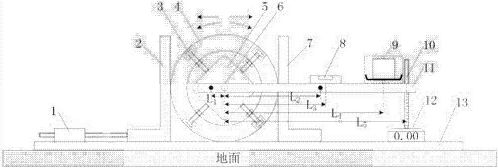
[0013] First embodiment: figure 1 Shown is the cogging torque measurement system for the case of a flat rail. The system components mainly include: precision mobile platform (1), baffles (2) and (7), circular housing (4) and positioning bolts (3), motor under test (5), level ruler (8), accessories Weight (9), screw rod (10), balance bar (11), electronic scale (12) and guide rail (13). The characteristics and measurement steps of the cogging torque measurement system are as follows.

[0014] 1. The motor under test (5) is adjusted to be located at the geometric center of the circular housing (4) through the positioning bolts (3), and the motor under test (5) is tightly connected to the circular housing (4); The motor (5) forms tangential contact with the guide rail (13) through the circular casing (4), and its position on the guide rail is positioned by means of the baffles (2) and (7).

[0015] 2. The motor shaft (6) is tightly connected to the balance bar (11), and the con...

no. 2 example

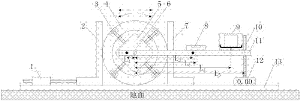
[0021] Second embodiment: figure 2 Shown is the cogging torque measurement system for the case of a sloped guide rail. Referring to the comparative first embodiment ( figure 1 ), the cogging torque measurement system for the slope guide rail case ( figure 2 ) of the characteristics and measurement steps are.

[0022] 1. From the system components, the cogging torque measurement system of the slope guide rail has added a slope pad (14). The slope pad (14) is used to pad one end of the guide rail (13) to form a slope guide rail; and the slope angle φ Meet: G m *sin( φ ) m , where G m is the gravity of the motor under test (5), F m is the maximum static friction force of the tested motor (5) on the guide rail (13).

[0023] 2. In terms of the movement process, when it needs to move on the guide rail (13), with the help of the slope and the limited slope angle, the motor under test (5) can roll on the guide rail (13) by itself relying on its own gravity.

[0024] 3. T...


PUM


Abstract

The invention belongs to the motor torque measuring technology and more particularly, to a permanent magnetic motor gullet torque measuring method, characterized by: a tested motor is in tangent contact with the guide rail plane through a circular housing and under the assistance of a baffle plate, positions at the position of the guide rail; when the guide rail moves, the tested motor rolls and through a precise moving platform, the moving length of the tested motor is determined; the motor shaft at the geometrical center of the circular housing ensures that the initial angle is possible at any measuring point through a horizontal balanced rod. The balanced rod is ensured to be at a horizontal state at any measuring point through the horizontal ruler, the counterweight, the screw rod support rod and the electronic scale. According to the lever balance principle and through the torque equilibrium equation, it is possible to accurately work out the gullet torque at any measuring point. Through the gradual movement and the measurement along the guide rail, the discrete waveform for the motor gullet torque could be obtained.

Description

technical field [0001] The invention belongs to the motor torque testing technology, in particular to the measurement of the cogging torque of a permanent magnet motor. Background technique [0002] Due to factors such as cogging structure and pole slot fit, the permeance distribution in the entire circumference of the motor will always be uneven. In a permanent magnet motor, however, the permanent magnet poles always tend to be positioned at the minimum permeance position. Therefore, the cogging torque based on the permanent magnet pole positioning effect is an inherent phenomenon of permanent magnet motors. Compared with the rated torque, the magnitude of the cogging torque is usually small, but its fluctuation frequency is usually high. When the motor is running, the high-frequency fluctuating cogging torque causes the increase of vibration and noise, the fluctuation of instantaneous torque and speed, etc., which is not conducive to the improvement of the performance of...

Claims


Application Information

Patent Timeline
Patent Type & Authority Applications(China)
IPC IPC(8): G01L3/00
CPCG01L3/00
Inventor 谢鸿钦肖先勇
Owner SICHUAN UNIV
Why Eureka
Try Eureka