Blower fan filter set and EFU surface wind speed uniformity automatic testing device and method

A technology of automatic test device and filter, applied in the direction of measurement device, fluid velocity measurement, velocity/acceleration/impact measurement, etc., can solve the problems of not realizing mechanical automation, airflow interference, reducing measurement efficiency, etc., and achieve mechanization and automation. , The probe position is precisely fixed, and the effect of reducing labor intensity

Inactive Publication Date: 2017-09-08
TONGJI UNIV
View PDF3 Cites 5 Cited by
  • Summary
  • Abstract
  • Description
  • Claims
  • Application Information

AI Technical Summary

Problems solved by technology

[0004] At present, the surface wind velocity uniformity of FFU and EFU is tested manually, and mechanical automation has not yet been realized.
Most of the testers measure the measuring points sequentially by hand-held anemometer probes. This measurement method will bring the following problems: on the one hand, the number of measuring points is large, the labor intensity is high, and the measurement efficiency is low; Large measurement errors, including inaccurate division of measurement points, uneven distribution of measurement time at each measurement point, easy fluctuations in the position of hand-held probes, large errors in manual readings, and interference by personnel themselves on airflow, etc.
However, this approach will obviously increase the measurement time and labor intensity, greatly reduce the measurement efficiency, and has no obvious improvement on the above-mentioned other factors that introduce errors

Method used


Image

  • Blower fan filter set and EFU surface wind speed uniformity automatic testing device and method
  • Blower fan filter set and EFU surface wind speed uniformity automatic testing device and method
  • Blower fan filter set and EFU surface wind speed uniformity automatic testing device and method

Examples


Embodiment

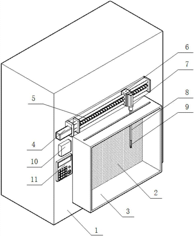
[0050] An automatic testing device for the surface wind speed uniformity of the fan filter unit and the equipment filter unit, the structure of which is as follows: figure 1 As shown, it includes a large static pressure box 1, a baffle 3, a linear guide rail mechanism, a telescopic rod mechanism, an anemometer probe 9, an anemometer 10 and a display controller 11.

[0051] The large plenum 1 is used to connect the auxiliary air system, install the FFU or EFU under test and deploy other components of the test facility. One side of the plenum box 1 is connected to the auxiliary air system, and the other side has an opening 2. The FFU or EFU under test is installed vertically in the plenum box 1, and the air is discharged from the opening 2 of the plenum box. When the size of the air outlet surface of the tested FFU or EFU is smaller than the size of the opening 2 of the plenum box, use the auxiliary plate for installation. In this example, the external dimensions of the tested ...


PUM


Abstract

The invention relates to a blower fan filter set and an EFU surface wind speed uniformity automatic testing device and a method, wherein the device comprises: an auxiliary wind system in connection with one side, a large scale static pressure chamber with an opening at the other side a baffle plate arranged on the circumference of the opening of the large scale static pressure chamber, a straight line guide rail mechanism horizontally arranged at the upper side of the opening of the static pressure chamber, a telescopic mechanism vertically arranged on the straight line guide rail mechanism, a wind speed probe arranged at the end of the telescopic rod mechanism, a wind speed instrument in connection with the wind speed probe, and a display controller in electric connection with the straight line guide rail mechanism, the telescopic rod mechanism, and the wind speed instrument. The method comprises: setting the delay time and the measurement time; inputting the dimension parameters related to the tested FFU or EFU; setting and choosing a proper testing point to deploy schemes; positioning the starting point of the measurement probe; waiting until the completion of the automatic testing and checking and exporting the testing result. Compared with the prior art, the device and the method of the invention can be operated conveniently, which increases the testing efficiency and the accuracy significantly.

Description

technical field [0001] The invention belongs to the technical field of air cleaning, and in particular relates to a device and method for automatically testing the surface wind speed uniformity of a fan filter unit and an equipment filter unit. Background technique [0002] Fan filter unit (Fan Filter Unit, FFU) is an air purification equipment with a built-in fan. It is mainly composed of a fan, high-efficiency or ultra-high-efficiency air filter, has a certain modulus size and standard specifications, and can be used with the ceiling frame. installation, and can be used in modular connections. Due to the advantages of flexible overall design, convenient installation and construction, simple and effective sealing method, and easy control, FFU has been widely used in the field of air cleaning. Demanding microenvironment or isolated work area. The equipment filter unit (Equipment Filter Unit, EFU) is basically the same structure as the FFU, and is mainly installed on the eq...

Claims


Application Information

Patent Timeline
Patent Type & Authority Applications(China)
IPC IPC(8): G01P5/00
CPCG01P5/00
Inventor 林忠平王登熊文浪王丽薇王永翔陈思华
Owner TONGJI UNIV
Why Eureka
Try Eureka