Device for alignment of infrared lens set under low temperature

A lens group and centering device technology, which is applied in installation, instrumentation, optics, etc., can solve the problems of high processing and preparation costs, high subsequent inspection and assembly and preparation costs, extremely high processing precision requirements, and inability to achieve lens group centering operations.

Active Publication Date: 2017-09-08
SHANGHAI INST OF TECHNICAL PHYSICS - CHINESE ACAD OF SCI
View PDF5 Cites 5 Cited by
  • Summary
  • Abstract
  • Description
  • Claims
  • Application Information

AI Technical Summary

Problems solved by technology

Due to the influence of assembly stress and the thermal expansion and contraction of the lens structure, the alignment accuracy at room temperature will inevitably appear at low temperature. Misalignment of alignment accuracy and unmeasurable deviations
In the preparation of traditional infrared lens groups, one method is to control the accuracy of centering by controlling the tolerance of parts and repeated assembly measurements. The cost is high; in addition, in the patent "A Method for Installing and Adjusting Infrared Lens" (public number: CN102998767A), a method of using a dual optical path measuring instrument for centering and adjusting the infrared lens is introduced
However, since the two methods cannot realize the centering operation of the lens group at low temperature, they cannot solve the problem of misalignment of the centering accuracy and unmeasurable deviation of the lens group when used at low temperature

Method used


Image

  • Device for alignment of infrared lens set under low temperature
  • Device for alignment of infrared lens set under low temperature
  • Device for alignment of infrared lens set under low temperature

Examples


Embodiment Construction

[0066] The specific embodiments of the present invention will be described in further detail below in conjunction with the accompanying drawings:

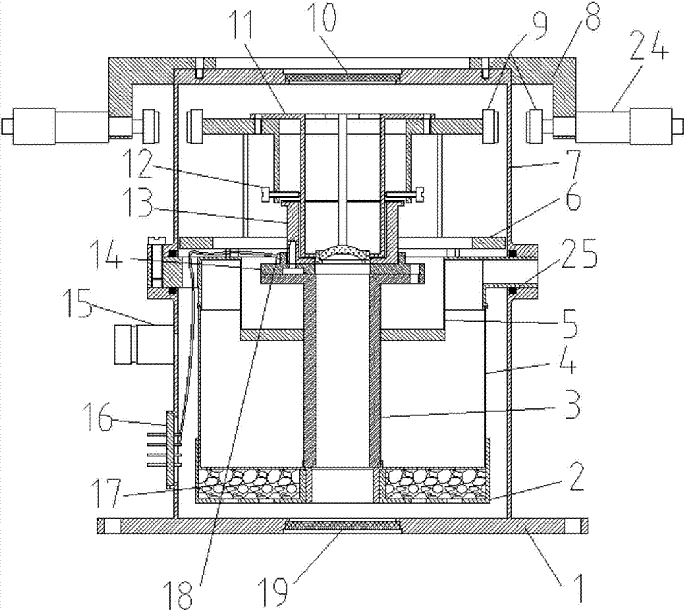
[0067] An example is the alignment and calibration of the lens group in a long-wave infrared detector assembly project. The lens group is integrated inside the detector assembly Dewar, and the operating temperature is 80K.

[0068] 1. The method for the preparation of each part in the present invention:

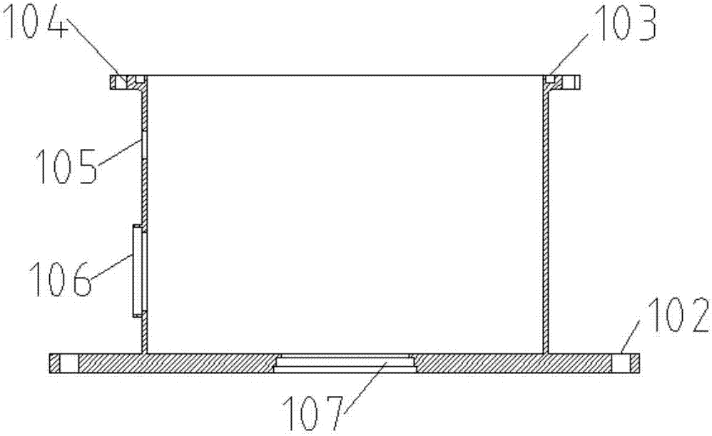
[0069] The material of the casing base 1 is stainless steel, the thickness of the barrel wall is 2mm, the height is 65mm, 8 fixing holes 102 with a diameter of 4.5mm are evenly distributed on the outer side of the bottom, and there is a base sealing ring groove 103 on the upper part, the groove width is 2mm, and the groove The depth is 1mm, the base mounting holes 104 are evenly distributed with 8 light holes with a diameter of 4.5mm in the circumferential direction, there are air extraction interface mounting holes 105 and lead ...


PUM


Abstract

The present invention discloses a device for alignment of an infrared lens set under low temperature. The device comprises a housing pedestal, a cold transferring copper cavity, a stock solution inner container, a strain adjusting rack, an installation cap, millesimal nuts, magnets, a lens set tube socket, a transition installation block, an air exhaust interface, a lead interface and a light transmission window. A cavity formed by the housing pedestal, the cold transferring copper cavity, the stock solution inner container and the installation cap is configured to provide low-temperature vacuum environment for an adjusted lens set. The magnets are arranged on the strain adjusting rack and the external portion of the housing to adjust the millesimal nuts arranged at the external portion of the device, and the repulsive force generated by changing the distance of the magnets is employed to drive the alignment fine tuning of the lens. A laser welder is employed to perform spot welding fixing of the fixed edges of the lens and the housing of the lens set after alignment to complete the alignment operation of the lens set in the low temperature. The problem of alignment adjusting of the infrared lens set in the low temperature is solved, and the precision of alignment, assembling and calibration is improved.

Description

technical field [0001] The invention relates to an infrared detector assembly packaging technology and an infrared lens group low-temperature optical alignment technology, in particular to an infrared lens group alignment device and an alignment method for working in a liquid nitrogen temperature region, which are suitable for infrared lenses used in an infrared detector assembly. Group centering adjustment operation at low temperature. Background technique [0002] The preparation technology of infrared detector components is of great significance in the fields of aerospace and aviation infrared. With the expansion of wavelengths to long wavelengths and the improvement of detection sensitivity, infrared detectors must work at deep and low temperatures, which also makes infrared detectors mostly use Dewar packages to form infrared detector Dewar components. In the development direction of the packaging technology of infrared detector components, one of the trends is the dev...

Claims


Application Information

Patent Timeline
Patent Type & Authority Applications(China)
IPC IPC(8): G02B7/02G02B7/00
CPCG02B7/003G02B7/007G02B7/02G02B7/023G02B7/028
Inventor 孙闻张珏颖张磊陈俊林王煜宇
Owner SHANGHAI INST OF TECHNICAL PHYSICS - CHINESE ACAD OF SCI
Why Eureka
Try Eureka