
Wireless remote control system for optical interferometer regulating device

A control device and optical interference technology, applied in the field of control, can solve the problem of no more than two meters, avoid the influence of airflow jitter, and realize the effect of non-contact control

Inactive Publication Date: 2017-09-08
UNIV OF SHANGHAI FOR SCI & TECH
View PDF2 Cites 0 Cited by
  • Summary
  • Abstract
  • Description
  • Claims
  • Application Information

AI Technical Summary

Problems solved by technology

[0003] At present, through the search of relevant information, ZYGO, a foreign advanced interferometer company, mainly controls the fine-tuning components of the interferometer through a wired remote control, and the length generally does not exceed two meters, so that the measurement personnel can only measure within the two-meter range. Carry out sample inspection

Method used


Image

  • Wireless remote control system for optical interferometer regulating device
  • Wireless remote control system for optical interferometer regulating device

Examples


Embodiment Construction

[0017] In order to make the technical means, creative features, goals and effects achieved by the present invention easy to understand, the following embodiments are combined with the accompanying drawings to explain the composition, working principle and beneficial effects of the wireless remote control system for the optical interferometer control device provided by the present invention. Be specific.

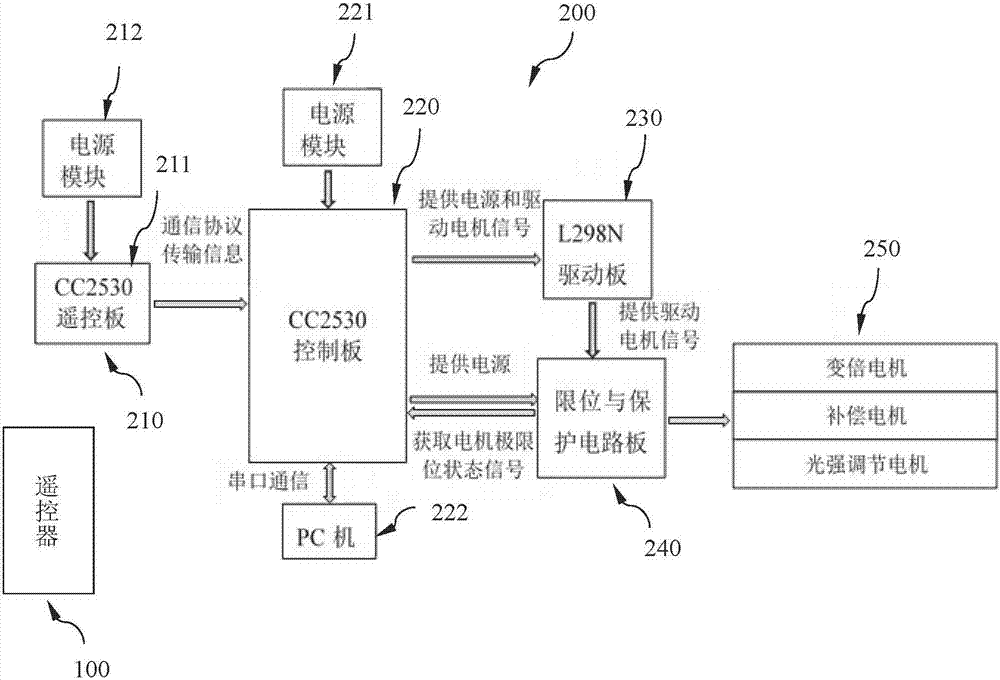
[0018] figure 1 It is a composition diagram of the wireless remote control system for the optical interferometer control device of the present invention.

[0019] Such as figure 1 As shown, the wireless remote control system 1 for the optical interferometer control device in this embodiment is composed of a remote control 100 and a remote control control device 200 .

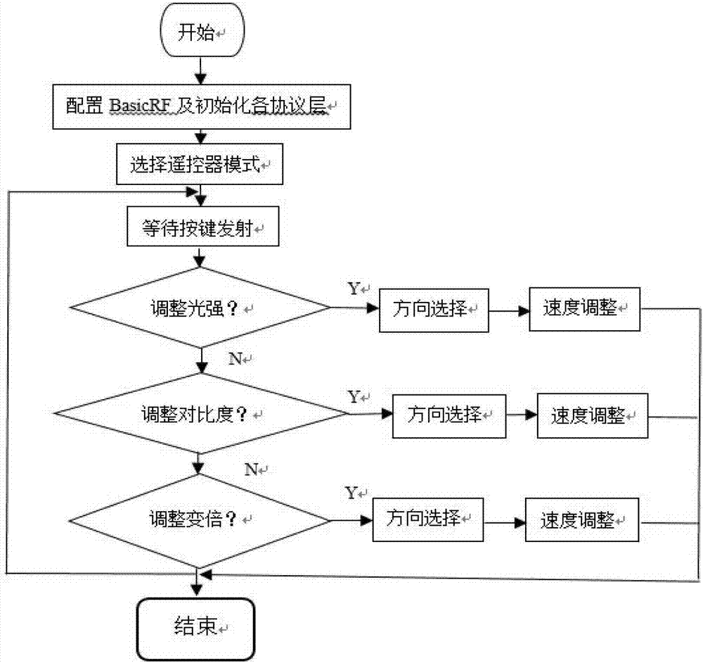
[0020] figure 2 It is an action flowchart of the remote controller in the present invention.

[0021] The remote controller 100 is used to send out radio waves containing remote control instructions, and i...


PUM


Abstract

The invention provides a wireless remote control system for an optical interferometer regulating device. The system comprises a remote controller and a remote control regulation device, the remote controller is used for sending remote control instruments, and the remote control regulation device is arranged in the optical interferometer regulating device and used for receiving the remote control instructions. The remote control regulation device comprises a remote control board, a control board, a motor driving circuit and a motor. The remote control board is used for receiving the remote control instructions; the control board is electrically connected with the remote control board and used for parsing the remote control instructions into corresponding control action instructions; the motor driving circuit comprises an input end and an output end, the input end is used for receiving the control action instructions and connected with the control board, and the output end is used for sending control current for directly controlling the motor; the motor is connected with a protective circuit board output port and further connected with an optical fine tuning element to drive the optical fine tuning element to regulate. Regulation of the optical interferometer regulating device can be realized by direction operation of the controller, and remote control distance can be adjusted conveniently by setting of different remote control signal intensities.

Description

technical field [0001] The invention relates to a wireless remote control system, in particular to a remote control system for controlling an optical interferometer control device, which belongs to the field of control. Background technique [0002] Optical interferometer is a high-precision and high-sensitivity optical detection equipment with interferometer measurement technology as the core. It has a wide range of applications in the fields of optics, electromechanical, chemical materials, precision machinery, and national metrology. With the development of opto-mechanical technology, the degree of automation and anti-interference of the interferometer is also continuously improved, especially the rapid development of communication technology and computer, which has greatly improved the precision control and anti-shock performance of the instrument. However, the degree of opto-mechanical integration of interferometers in my country is relatively low at present. In the pro...

Claims


Application Information

Patent Timeline
Patent Type & Authority Applications(China)
IPC IPC(8): G08C17/02G01B9/02
CPCG08C17/02G01B9/02
Inventor 韩森卢庆杰唐寿鸿王芳王全召李雪园
Owner UNIV OF SHANGHAI FOR SCI & TECH
Learn More