Temperature compensation circuit for radio frequency power amplifier
A temperature compensation circuit, radio frequency power technology, applied in power amplifiers, radio frequency amplifiers, improving amplifiers to reduce temperature/power supply voltage changes, etc. Weakening effects, addressing the effects of amplifying linear variation, improving stability and work efficiency
- Summary
- Abstract
- Description
- Claims
- Application Information
AI Technical Summary
Problems solved by technology
Method used
Image
Examples
Embodiment 1
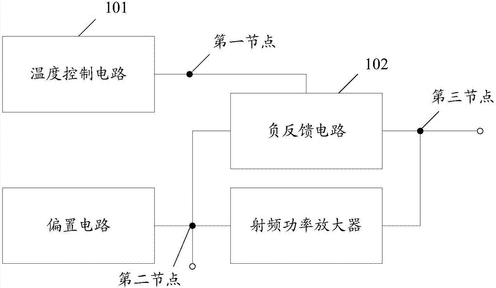
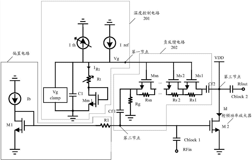
[0062] In Embodiment 1 of the present invention, the specific composition and structure of the temperature compensation circuit of the RF power amplifier is as follows figure 2 As shown, the temperature compensation circuit includes a temperature control circuit 201 and a negative feedback circuit 202 .
[0063] The temperature control circuit 201 includes a temperature control power supply, a steady state power supply, a clamp circuit, a filter circuit and an adjustable resistance circuit.
[0064] The temperature-controlled power supply is connected to the adjustable resistance circuit through the first node, and is used to provide the adjustable resistance circuit with an electrical signal that changes with temperature; the electrical signal of the temperature-controlled power supply is proportional to the absolute temperature Proportional.
[0065] The steady-state power supply is connected to the adjustable resistance circuit through the first node, and is used to provi...
Embodiment 2
[0102] In Embodiment 2 of the present invention, the specific composition and structure of the temperature compensation circuit of the RF power amplifier is as follows Figure 9As shown, the temperature compensation circuit 901 includes a temperature control circuit 901a and a negative feedback circuit 901b. The specific composition and structure of the temperature control circuit 901a is the same as that of the temperature control circuit 201 in Embodiment 1, which will not be repeated here.
[0103] The negative feedback circuit 901b includes an inverter group circuit, a transistor group circuit, a parallel resistance circuit, a first capacitor and a second capacitor;
[0104] The inverter group circuit includes m inverters, the output end of each inverter is connected to the input end of each transistor group in the transistor group circuit, and the input end of each inverter is connected to the The first nodes are connected to transmit the second electrical signal to the t...
Embodiment 3
[0120] In the third embodiment of the present invention, the specific composition and structure of the radio frequency power amplifier circuit is as follows Figure 10 As shown, the temperature compensation circuit 1001 and the bias circuit 1003 may be implemented in any one of the first and second embodiments, which will not be repeated here.
[0121] The radio frequency power amplifier 1003 includes n amplifying transistors, the n amplifying transistors are connected in series, and the input terminal of each transistor is connected to the second node, and the n transistors can be represented as M21, M22, ..., M2k, where k is a positive integer greater than 1, the source of M2k is connected to the third node, the drain of M21 is grounded, and the power gain of the RF power amplifier is the total gain after the amplifier transistors are connected in series.
PUM
 Abstract
Description
Claims
Application Information
 - R&D
- Intellectual Property
- Life Sciences
- Materials
- Tech Scout
- Unparalleled Data Quality
- Higher Quality Content
- 60% Fewer Hallucinations
Browse by: Latest US Patents, China's latest patents, Technical Efficacy Thesaurus, Application Domain, Technology Topic, Popular Technical Reports.
© 2025 PatSnap. All rights reserved.Legal|Privacy policy|Modern Slavery Act Transparency Statement|Sitemap|About US| Contact US: help@patsnap.com


