Optical module

A technology of optical modules and optical fibers, which is applied in the field of optical modules and can solve problems such as low optical coupling efficiency of optical modules

Active Publication Date: 2017-09-12
HISENSE BROADBAND MULTIMEDIA TECH
View PDF5 Cites 6 Cited by
  • Summary
  • Abstract
  • Description
  • Claims
  • Application Information

AI Technical Summary

Problems solved by technology

[0008] The embodiment of the present invention provides an optical module, which is used to solve the technical problem in the prior art that the optical module r

Method used


Image

  • Optical module
  • Optical module
  • Optical module

Examples


Embodiment Construction

[0032] In order to make the purpose, technical solutions and advantages of the present invention clearer, the present invention will be further described in detail below in conjunction with the accompanying drawings. Obviously, the described embodiments are only some of the embodiments of the present invention, rather than all of them. Based on the embodiments of the present invention, all other embodiments obtained by persons of ordinary skill in the art without making creative efforts belong to the protection scope of the present invention.

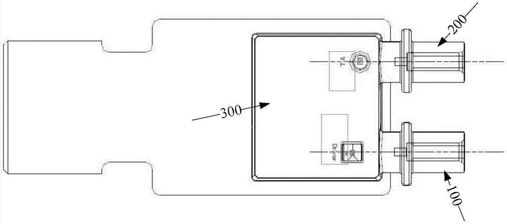
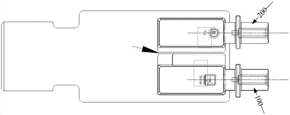
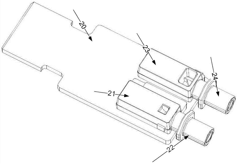
[0033] In order to solve the technical problem that the reflective end of the optical module and the lens assembly of the receiving end are integrated on the circuit board in the prior art, the difficulty of optical coupling of the optical module is increased, resulting in a low optical coupling efficiency of the optical module. An embodiment of the present invention provides an optical module, which keeps the distance between the optica...


PUM


Abstract

The present invention discloses an optical module comprising a circuit board, a first lens assembly and a laser chip. The first lens assembly is arranged above the laser chip; the first lens assembly includes a first optical fiber jack, a first reflective surface and a second reflective surface; the first optical fiber jack is for inserting the first optical fiber and the projection of the central axis of the first optical fiber jack on the circuit board does not pass through the center of the effective light emitting surface of the laser chip; the first reflecting surface is for receiving the first incident light signal from the laser chip so that the first incident light signal is reflected on the first reflecting surface to obtain a first reflected light signal; and the second reflecting surface is for receiving the first reflected light signal such that the first reflected light signal is reflected on the second reflecting surface to obtain a second reflected light signal and the second reflected light signal is transmitted through the second lens assembly and received by the first optical fiber. The optical module can realize independent lens assembly package of transmission and reception ends, thereby improving the optical coupling efficiency of the transmission end and the reception end of the optical module.

Description

technical field [0001] Embodiments of the present invention relate to the technical field of optical fiber communication, and in particular, to an optical module. Background technique [0002] The SFP+ optical module includes an optical transmitting sub-module for transmitting optical signals and an optical receiving sub-module for receiving optical signals. The lens assembly of the optical module is packaged in one package, such as Figure 1a The shown optical module includes a light emitting sub-module 100, a light receiving sub-module 200, and an integrated packaged optical module lens assembly 300. In the optical module lens assembly 300, the transmitting end lens assembly corresponding to the light emitting sub-module includes a drive chip Drive and laser, the receiving end lens assembly corresponding to the light receiving sub-module includes a drive chip TIA and a detector PD, and the transmitting end lens assembly and the receiving end lens assembly are integrally pac...

Claims


Application Information

Patent Timeline
IPC IPC(8): G02B6/42
CPCG02B6/4204G02B6/4214G02B6/4296
Inventor 刘旭霞黄永亮邵乾
Owner HISENSE BROADBAND MULTIMEDIA TECH
Why Eureka
Try Eureka