Resource allocation control method, device and system

A technology of resource allocation and control method, applied in the field of resource allocation control method, device and system, can solve the problem of low resource utilization rate and the like

Active Publication Date: 2017-09-12
ZTE CORP
View PDF5 Cites 5 Cited by
  • Summary
  • Abstract
  • Description
  • Claims
  • Application Information

AI Technical Summary

Problems solved by technology

[0006] The present invention provides a resource allocation control method, device, and system method and device to at least solve the problem of low resource utilization in the related art when performing carrier aggregation between cells

Method used


Image

  • Resource allocation control method, device and system
  • Resource allocation control method, device and system
  • Resource allocation control method, device and system

Examples


Embodiment 1

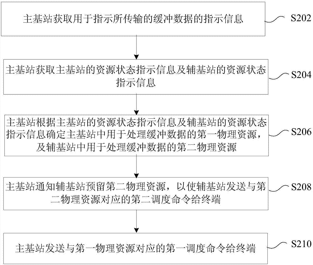
[0051] In this embodiment, a resource allocation control method is provided, figure 2 is a flow chart of an optional resource allocation control method according to an embodiment of the present invention, such as figure 2 As shown, the process includes the following steps:

[0052] Step S202, the main base station acquires indication information for indicating the transmitted buffered data, where the buffered data includes uplink buffered data sent by the terminal or downlink buffered data sent to the terminal;

[0053] Step S204, the master base station acquires resource status indication information of the master base station and resource status indication information of the secondary base station, wherein the terminal respectively establishes a communication connection with the first cell in the master base station and the second cell in the secondary base station;

[0054] Step S206, the primary base station determines the first physical resource for processing buffered...

Embodiment 2

[0148] In this embodiment, a resource allocation control method is provided, Figure 5 is a flowchart of another optional resource allocation control method according to an embodiment of the present invention, such as Figure 5 As shown, the process includes the following steps:

[0149] Step S502, the secondary base station sends resource status indication information of the secondary base station to the primary base station, wherein the first cell in the primary base station and the second cell in the secondary base station have established communication connections with the terminal, and the primary base station is used to The resource status indication information and the resource status indication information of the secondary base station determine the first physical resource for processing buffered data in the primary base station, and the second physical resource for processing buffered data in the secondary base station, so that the primary base station The first sche...

Embodiment 3

[0156] In this embodiment, a resource allocation control device is also provided, which is applied to the main base station, and the device is used to implement the above embodiments and preferred implementation modes, and what has been described will not be repeated. As used below, the term "module" may be a combination of software and / or hardware that realizes a predetermined function. Although the devices described in the following embodiments are preferably implemented in software, implementations in hardware, or a combination of software and hardware are also possible and contemplated.

[0157] Figure 6 is a structural block diagram of an optional resource allocation control device according to an embodiment of the present invention, such as Figure 6 As shown, the device includes:

[0158] 1) The first acquiring module 602 is configured to acquire indication information for indicating the transmitted buffered data, where the buffered data includes uplink buffered data...


PUM


Abstract

The invention provides a resource allocation control method, device and system, wherein the method comprises the steps that: a primary base station obtains indication information used for indicating transmitted buffer data; the primary base station obtains the resource state indication information of the primary base station and the resource state indication information of a secondary base station; according to the resource state indication information of the primary base station and the resource state indication information of the secondary base station, the primary base station determines a first physical resource used for processing the buffer data in the primary base station, and a second physical resource used for processing the buffer data in the secondary base station; the primary base station notifies the secondary base station to reserve the second physical resource; therefore, the secondary base station sends a second scheduling command corresponding to the second physical resource to a terminal; and the primary base station sends a first scheduling command corresponding to the first physical resource to the terminal. By means of the resource allocation control method, device and system provided by the invention, the problem that the resource utilization rate is relatively low due to the fact that carrier aggregation is carried out between cells in the related technology can be solved; and thus, the resource utilization rate when carrier aggregation is carried out between the cells is increased.

Description

technical field [0001] The present invention relates to the communication field, in particular, to a resource allocation control method, device and system. Background technique [0002] In the long term evolution system (Long Term Evolution, referred to as LTE), according to the related technology, the protocol architecture of the user equipment or terminal (User Equipment, referred to as UE) side user plane is as follows: figure 1 shown. From bottom to top, it is divided into the following protocol layers: physical layer (Physical layer, referred to as PHY), media access control layer (MediaAccess Control, referred to as MAC), radio link control layer (Radio Link Control, referred to as RLC) ), Packet Data Convergence Protocol (PDCP for short). Among them, the PHY layer mainly transmits information to the MAC layer or higher layers through the transmission channel; the MAC layer mainly provides data transmission and wireless resource allocation through logical channels, a...

Claims


Application Information

Patent Timeline
Patent Type & Authority Applications(China)
IPC IPC(8): H04L5/00
CPCH04L5/0044H04L5/0091H04L5/00H04W72/12
Inventor 陈中明张娟吴昱民
Owner ZTE CORP
Why Eureka
Try Eureka