Combined slag removal system for grillage machine, and plate-mesh composite lateral-water-inflow grillage

A combination and grid machine technology, applied in the field of sewage pretreatment research, can solve problems such as easy clogging and difficult removal, and achieve the effects of simple operation, safe operation, and improved decontamination efficiency

Pending Publication Date: 2017-09-15
JIANGSU TIANYU ENVIRONMENTAL PROTECTION GRP CO LTD
View PDF8 Cites 6 Cited by
  • Summary
  • Abstract
  • Description
  • Claims
  • Application Information

AI Technical Summary

Problems solved by technology

[0005] The purpose of the present invention is to provide a combined slag removal system for the grid machine and a composite lateral flow water inlet grid for the grid machine, aiming at solving the problem of easy clogging and difficult removal of suspended matter such as fine fibers and hair. question

Method used


Image

  • Combined slag removal system for grillage machine, and plate-mesh composite lateral-water-inflow grillage
  • Combined slag removal system for grillage machine, and plate-mesh composite lateral-water-inflow grillage
  • Combined slag removal system for grillage machine, and plate-mesh composite lateral-water-inflow grillage

Examples


Embodiment approach

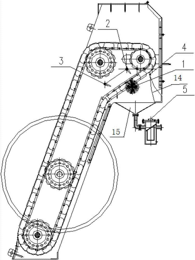
[0032] figure 1 Shown is an embodiment of a combined slag removal system for a grid machine according to the present invention. The combined slag removal system for a grid machine includes a rotating brush 1, a water flushing device 2, and an air flushing device 3. Rubber scraper 4 and hair collector 5.

[0033] The rotating brush 1 is located at the lower end outside the grid in the slag removal area, the rubber scraper 4 is located at the upper end outside the grid in the slag removal area; the water washing device 2 is located at the upper end inside the grid in the slag removal area, and the air washing device 3 is located at the inner lower end of the grid in the slag removal area; the rotating brush 1 is located at the grid in the slag removal area opposite between the water flushing device 2 and the air flushing device 3; the rubber scraper 4 is connected with an arc-shaped deflector 14, The arc-shaped deflector 14 leads to the bottom of the slag removal area; the hair...


PUM

PropertyMeasurementUnit
thicknessaaaaaaaaaa

Abstract

The invention provides a combined slag removal system for a grillage machine, and a plate-mesh composite lateral-water-inflow grillage provided with the combined slag removal system. The combined slag removal system comprises a rotary hairbrush, a water flushing apparatus, an air flushing apparatus, a rubber scraper plate and a hair collector, wherein the rotary hairbrush is located at the lower end of the outer side of a grid mesh in a slag removal zone; the rubber scraper plate is located at the upper end of the outer side of the grid mesh in the slag removal zone; the water flushing apparatus is located at the upper end of the inner side of the grid mesh in the slag removal zone; the air flushing apparatus is located at the lower end of the inner side of the grid mesh in the slag removal zone; an arc flow deflector is arranged below and connected with the rubber scraper plate and guides flow to the bottom end of the slag removal zone; the hair collector is communicated with the bottom end of the slag removal zone; and the bottom end of the slag removal zone is located below the rotary hairbrush. According to the invention, the rubber scraper plate is used at first for separating large-grain substances from fine suspended solids like fibers and hair, and the large-grain substances is removed along the flow deflector in virtue of the gravity of the large-grain substances; and the fibers and hair are allowed to depart from the grid mesh under the co-action of the water flushing apparatus, the air flushing apparatus and the rotary hairbrush and then enter the hair collector along with water flow, so high-efficiency removal of residues in the grillage machine is realized.

Description

technical field [0001] The invention belongs to the research field of sewage pretreatment, and in particular relates to a combined slag removal system of a grid machine and a plate-mesh composite side flow water inlet grid. Background technique [0002] Fine suspended solids such as fibers and hair are abundant in domestic sewage, aquaculture wastewater, and industrial wastewater such as textiles. If not treated, it will have a great impact on the normal and efficient operation of sewage subsequent treatment facilities. In the sewage treatment process, the grid machine is a necessary pretreatment equipment before the sewage enters the treatment facility, and its treatment effect largely depends on the performance of the slag removal system. [0003] In the existing technology, the traditional screen machine mainly removes larger suspended solids in sewage, and has poor removal effect on suspended matter such as fine fibers and hair, and the problem that the slag removal syst...

Claims


Application Information

Patent Timeline
Patent Type & Authority Applications(China)
IPC IPC(8): C02F1/00B01D33/76B01D33/72B01D33/333B01D33/46B01D33/48
CPCB01D33/333B01D33/461B01D33/48B01D33/72B01D33/76C02F1/001
Inventor 王旗军曹贵华潘庆权王明根
Owner JIANGSU TIANYU ENVIRONMENTAL PROTECTION GRP CO LTD
Why Eureka
Try Eureka