Mutual-lock hammer valve mechanism for improving working performance of hydraulic impactor

A technology of hydraulic impactor and working performance, which is applied to the driving device for drilling in the wellbore, drilling equipment, earthwork drilling and production, etc. It can solve the problems of the hammer valve being separated from closing and not being tight, so as to ensure the reliability and sealing , Improve working performance, improve the effect of closing and sealing performance

Active Publication Date: 2017-09-15
BEIJING RES INST OF URANIUM GEOLOGY
View PDF4 Cites 3 Cited by
  • Summary
  • Abstract
  • Description
  • Claims
  • Application Information

AI Technical Summary

Problems solved by technology

[0003] The purpose of the present invention is to provide an interlocking hammer valve mechanism that can improve the working performance of the hydraulic impactor, to ensure the reliable coordination between the hammer rod and the live valve in the stroke and return process, and to solve the problem of the existing double-acting valve mechanism. During the working process of the hydraulic impactor, the hammer valve is separated early and the technology is not closed tightly, which can improve the working reliability of the hydraulic impactor, improve the utilization rate of water energy, and improve the working performance of the hydraulic impactor

Method used


Image

  • Mutual-lock hammer valve mechanism for improving working performance of hydraulic impactor

Examples


Embodiment Construction

[0008] The present invention will be described in further detail below in conjunction with the accompanying drawings and embodiments.

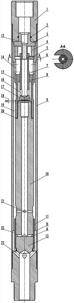
[0009] As shown in Figure 1, the interlocking hammer valve mechanism provided by the present invention can improve the working performance of the hydraulic impactor. The interlocking hammer valve mechanism includes an upper joint 1, a sealing ring 2, a drainage tube 3, and a positioning sleeve 4 , limit pad 5, upper guide sleeve 6, live valve 7, upper joint 8 of the hammer rod, outer pipe 9, hammer rod 10, lower cylinder liner 11, impact anvil 12. The upper joint 1 and the outer pipe 9 are rigidly connected by thread, and the lower part of the connecting thread of the outer pipe 9 is processed with an inner hole concentric with the diameter of the thread and a limit step. The upper guide sleeve 6 is put into the inner hole from the upper opening of the outer pipe 9 Inside, the outer diameter of the upper guide sleeve 6 is sliding and sealed wi...


PUM


Abstract

The invention belongs to the field of drilling machinery, and particularly discloses a mutual-lock hammer valve mechanism for improving the working performance of a hydraulic impactor. The upper of a drainage tube is inserted in the bottom of an upper connecting head, and the lower portion of the drainage tube is inserted in the top of an active valve. The top of the active valve is externally clamped in a limiting pad. A positioning sleeve is arranged between the bottom surface of a boss in the middle of the drainage tube and the limiting pad. The lower portion of the active valve is provided with a hammer-impacting rod. The outer portions of the active valve and the hammer-impacting rod are sleeved with hammer-impacting rod upper section connecting heads. The active valve is slidably matched with an inner hole of the hammer-impacting rod upper section connecting heads. The top of the hammer-impacting rod and the connecting heads of the upper section of the hammer-impacting rod are fixedly connected. The hammer-impacting rod and the hammer-impacting rod upper section connecting heads constitute a hammer-impacting assembly. The lower portion of the hammer-impacting rod is provided with an impacting anvil bed. A lower cylinder sleeve is externally sleeved with the bottom of the hammer-impacting rod. The bottom of the upper connecting head is sleeved with the top of an outer tube. The impacting anvil bed is sleeved with the bottom of the outer tube. According to the mutual-lock hammer valve mechanism, the closing and sealing performance of an impacting hammer and the active valve of the hydraulic impactor is improved, the synchronization coordination and reliability of the combination of the hammer and the valve are ensured, and the water power utilization ratio and working performance of the hydraulic impactor are improved.

Description

technical field [0001] The invention belongs to the field of drilling machinery, and in particular relates to a valve control mechanism of a hydraulic impactor used in the fields of geological and mineral resource drilling, oil drilling, hydrological water well drilling and engineering construction. Background technique [0002] The valve-type double-acting hydraulic impactor is the most researched and most widely used hydraulic impactor. It is installed on the rotary drilling tool as an auxiliary rock breaking tool and is widely used in drilling and drilling fields. It is beneficial to improve drilling efficiency, increase the rate of core recovery, prevent the jamming of drilling tools in broken rock formations, increase the service life of drill bits, and control the deviation of drilling holes. It makes use of the difference in area or the pressure difference generated by the negative pressure entrainment of the jet, so that the live valve reaches the upper limit positi...

Claims


Application Information

Patent Timeline
Patent Type & Authority Applications(China)
IPC IPC(8): E21B4/14
CPCE21B4/14
Inventor 刘晓阳段隆臣李博李生海
Owner BEIJING RES INST OF URANIUM GEOLOGY
Why Eureka
Try Eureka