Eureka AIR delivers breakthrough ideas for toughest innovation challenges, trusted by R&D personnel around the world.

Annular laser-electromagnetic ultrasonic focusing probe

An electromagnetic ultrasonic and focusing probe technology, which is applied to the analysis of solids using sound waves/ultrasonic waves/infrasonic waves, material analysis using sound waves/ultrasonic waves/infrasonic waves, and measurement devices. , Beam energy distribution is not concentrated, etc., to achieve the effect of compact structure, easy to move and operate, improve receiving efficiency and signal-to-noise ratio

Active Publication Date: 2017-09-15
广东省傲来科技有限公司
View PDF9 Cites 10 Cited by
  • Summary
  • Abstract
  • Description
  • Claims
  • Application Information

AI Technical Summary

Problems solved by technology

However, due to the strong surface waves generated in metal materials in the laser ultrasonic thermoelastic mode, the body waves are weak and the beam energy distribution is not concentrated
Therefore, laser-electromagnetic ultrasound is currently mainly used for the detection of surface defects, and it is more difficult to detect internal defects.
In addition, the current laser-electromagnetic ultrasonic testing technology at home and abroad adopts the one-shot-one-retract split-body detection mode, that is, the laser and electromagnetic ultrasonic probes are located at different positions of the specimen, resulting in an uncompact design of the entire probe device and inconvenient operation.

Method used


Image

  • Annular laser-electromagnetic ultrasonic focusing probe
  • Annular laser-electromagnetic ultrasonic focusing probe
  • Annular laser-electromagnetic ultrasonic focusing probe

Examples


Embodiment Construction

[0012] The present invention will be described in further detail below in conjunction with the accompanying drawings and specific embodiments.

[0013] The present invention will be further described below with examples in conjunction with the accompanying drawings.

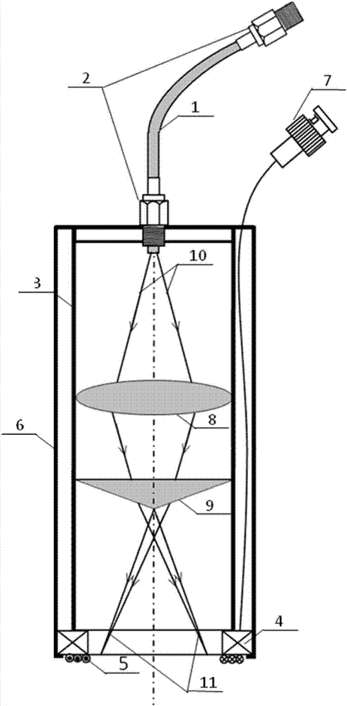
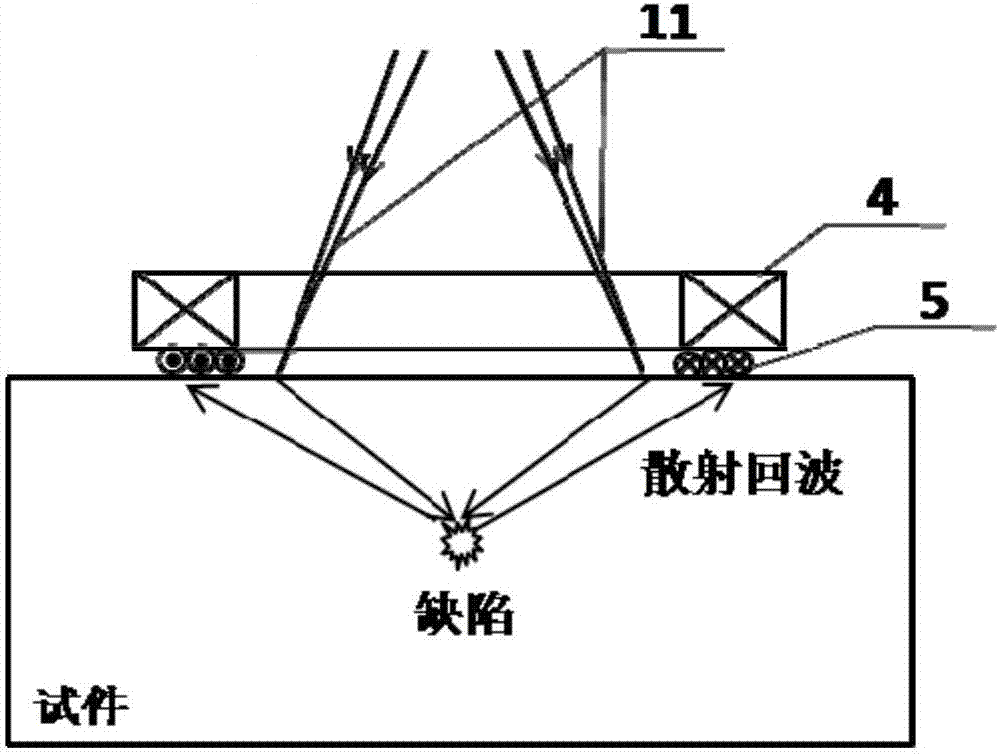
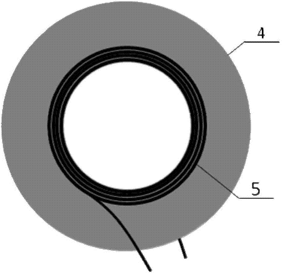
[0014] Such as figure 1 As shown, a ring laser-electromagnetic ultrasonic focusing probe of the present invention includes a probe housing 6, an optical lens group 3 fixed in the probe housing 6, and is connected to the top of the probe housing 6 through an SMA optical fiber interface 2 for introducing a single beam laser source The optical fiber 1 of 10 is fixed on the annular permanent magnet 4 at the bottom of the probe housing 6, and the annular receiving coil 5 attached to the bottom of the annular permanent magnet 4 is concentrically connected to the shielded wire 7 of the annular receiving coil 5; the single beam laser introduced by the optical fiber 1 The source 10 coincides with the optical axis of the ...


PUM


Abstract

The invention provides an annular laser-electromagnetic ultrasonic focusing probe which comprises a probe shell, an optical lens group, an optical fiber, an annular permanent magnet, an annular receiving coil and an annular focusing laser beam. The optical lens group is fixed in the probe shell, the optical fiber is connected at the top of the probe shell and used for leading in a single-beam laser source, the annular permanent magnet is fixed at the bottom of the probe shell, the annular receiving coil is centrally pasted at the bottom of the annular permanent magnet, the single-beam laser source led-in by the optical fiber is coincided with an optical axis of the optical lens group, the annular focusing laser beam is formed at a probe outlet and used for exciting focusing ultrasonic waves in a metal sample, and the inner diameter of the annular permanent magnet and the annular receiving coil is larger than the outer diameter of the annular focusing laser beam. According to the focusing probe, the optical lens group generates annular lasers, ultrasonic body waves of point focusing can be excited, focusing ultrasonic echo signals are received by the aid of the annular permanent magnet and the annular receiving coil, integral transceiving is achieved, and the capability for detecting defects of metal structure bodies is enhanced. The probe is compact in structure, convenient to move and operate and high in detection efficiency and can be used for detecting inner defects of metal materials.

Description

technical field [0001] The invention relates to a non-contact ultrasonic detection technology, in particular to a ring laser-electromagnetic ultrasonic focusing probe, which can be used for detection and evaluation of internal defects of metal materials. Background technique [0002] The laser-electromagnetic ultrasonic testing method is a composite non-contact ultrasonic testing technology that uses pulsed lasers to excite ultrasonic waves and uses electromagnetic ultrasonic probes to receive ultrasonic signals. This method combines the advantages of high laser ultrasonic excitation efficiency, wide frequency band, high electromagnetic ultrasonic detection sensitivity, and little influence on the surface state of the test piece, and has great application potential. However, due to the strong surface waves generated in metal materials under the laser ultrasonic thermoelastic mode, the body waves are weak and the beam energy distribution is not concentrated. Therefore, laser...

Claims


Application Information

Patent Timeline
Patent Type & Authority Applications(China)
IPC IPC(8): G01N29/04G01N29/24
CPCG01N29/04G01N29/24G01N2291/0234
Inventor 裴翠祥弋东驰刘天浩陈振茂
Owner 广东省傲来科技有限公司
Why Eureka
Eureka Blog
Learn More