High-brightness holographic waveguide display device

A holographic waveguide and display device technology, which is applied in light guides, optics, instruments, etc., can solve the problems of small brightness gain, color crosstalk, and more stray light in color display, so as to improve display brightness, solve insufficient display brightness, increase Effect of Spectral Bandwidth

Active Publication Date: 2017-09-15
SOUTHEAST UNIV
View PDF4 Cites 22 Cited by
  • Summary
  • Abstract
  • Description
  • Claims
  • Application Information

AI Technical Summary

Problems solved by technology

[0003] In the prior art, by using a volume holographic grating as the holographic waveguide structure of the outgoing and incoming couplers, the brightness of the exit pupil of the holographic waveguide display device is too low due to the angular selectivity and wavelength selectivity of the volume holographic grating, which cannot meet the requirement of enhancement. Requirements of Realistic Systems for the Brightness of Virtual Images
[0004] In addition, some people have proposed that the in-coupling end is a double-sided holographic grating structure. This solution increases the display brightness by adding a deviation angle to the inclination angle of the in-coupling end volume holographic grating, but this method will lead to more stray light. , and when the deviation angle is large, the color crosstalk problem is more serious for color display, and the brightness gain is small, and it cannot meet the requirements of the augmented reality system for the virtual image brightness

Method used


Image

  • High-brightness holographic waveguide display device
  • High-brightness holographic waveguide display device
  • High-brightness holographic waveguide display device

Examples


Embodiment Construction

[0019] The technical solutions of the present invention will be described in detail below in conjunction with the accompanying drawings.

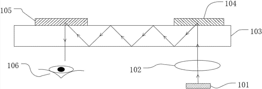
[0020] Such as figure 1 As shown, a holographic waveguide display device in the prior art includes a microdisplay 101 , a collimating mirror 102 , a waveguide 103 , an in-coupling volume holographic grating 104 and an out-coupling volume holographic grating 105 . The microdisplay 101 of the device emits divergent light carrying image information, and the divergent light passes through the collimating mirror 102 and turns into parallel light. The diffracted light formed by the diffraction of the holographic grating enters the waveguide 103 , and the diffracted light propagates in the form of total reflection in the waveguide until it is diffracted by the out-coupling volume holographic grating to output parallel light and enters the human eye 106 . Because the higher the diffraction efficiency of the volume holographic grating is, the narro...


PUM


Abstract

The invention discloses a high-brightness holographic waveguide display device which comprises a micro display device, a collimating mirror, a waveguide, an incident coupler and an outgoing coupling member holographic grating. The incident coupler comprises a top-layer holographic grating and a bottom-layer holographic grating. The top-layer holographic grating and the outgoing coupling member holographic grating are tightly connected with two ends of the first surface of the waveguide. The bottom-layer holographic grating is closely connected with the second surface of the waveguide and is arranged below the top-layer holographic grating. The top-layer holographic grating and the bottom-layer holographic grating realize Bragg diffraction on an incident light beam and the incident light beam enters the waveguide. The incident light beam is transmitted in a total reflection manner until the light beam is diffused and output by the outgoing holographic grating. Compared with the prior art, the high-brightness holographic waveguide display device increases spectral bandwidth and improves display brightness of the holographic waveguide display device under a precondition that the peak diffraction efficiency of the holographic grating does not reduce.

Description

technical field [0001] The invention relates to a waveguide display device, in particular to a high-brightness holographic waveguide display device. Background technique [0002] The holographic waveguide display device belongs to the field of head-mounted enhancement technology, and its key technology is to replace traditional optical elements with holographic optical elements as waveguide couplers to form a wearable imaging system with high integration. [0003] In the prior art, by using a volume holographic grating as the holographic waveguide structure of the outgoing and incoming couplers, the brightness of the exit pupil of the holographic waveguide display device is too low due to the angular selectivity and wavelength selectivity of the volume holographic grating, which cannot meet the requirement of enhancement. Real system requirements for virtual image brightness. [0004] In addition, some people have proposed that the in-coupling end is a double-sided holograp...

Claims


Application Information

Patent Timeline
Patent Type & Authority Applications(China)
IPC IPC(8): G02B27/01G02B6/122G02B5/32
CPCG02B5/32G02B6/1226G02B27/0103G02B27/0172G02B2027/0105G02B2027/0118G02B2027/0134G02B2027/0174G03H2001/2226
Inventor 王垒屠彦杨兰兰郭静菁石在耀张瑞文
Owner SOUTHEAST UNIV
Why Eureka
Try Eureka