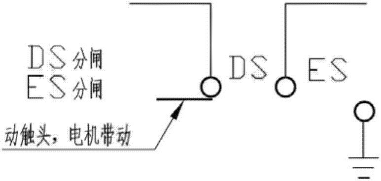
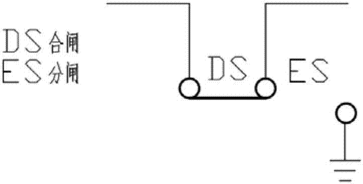
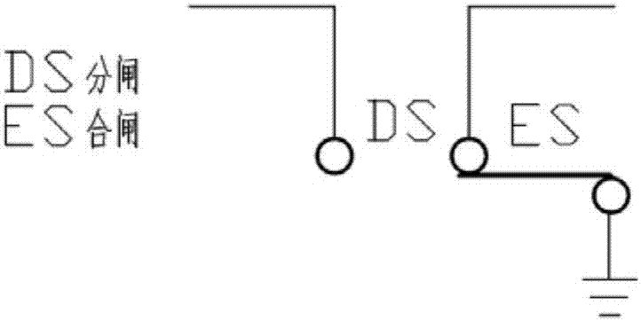
Motor control circuit of three-position switch operation mechanism

A technology of motor control and switch operation, applied in motor control, contact operating mechanism, power device inside the switch, etc., can solve the problem of high failure rate of motor braking, achieve accurate braking, low failure rate, and simple circuit principle Effect

Active Publication Date: 2017-09-15
HENAN PINGGAO ELECTRIC +2
View PDF6 Cites 9 Cited by
  • Summary
  • Abstract
  • Description
  • Claims
  • Application Information

AI Technical Summary

Problems solved by technology

[0006] The purpose of the present invention is to provide a motor control circuit of a three-position switch operating mechanism, which is used to solve the problem of high

Method used


Image

  • Motor control circuit of three-position switch operation mechanism
  • Motor control circuit of three-position switch operation mechanism
  • Motor control circuit of three-position switch operation mechanism

Examples


Embodiment 1

[0032] Such as Figure 4 As shown, it includes the first branch connected in series by the first closing normally open contact KE1', the interface D1', the interface D2', the second closing normally open contact KE2', the interface D3' and the interface D4', The first closing normally open contact KE1', the two ends of the interface D1', D2' are connected in parallel with the first opening normally open contact KA1', the interfaces D1', D2' and the second closing normally open contact KE2' There is a second opening normally open contact KA2' connected in parallel at both ends of the switch. Among them, the interfaces D1' and D2' are used to connect the rotor winding Mz of the motor, and the interfaces D3' and D4' are used to connect the stator winding Md of the motor.

[0033] The circuit also includes a second branch comprising a switch module K1 and a switch KL1 for switching positions such as Figure 4 As shown, the switch module K1 includes the third closing normally clo...

Embodiment 2

[0039] Such as Figure 5 As shown, in this embodiment, the forward and reverse rotation of the motor is judged through the actions of different contactors, and a relay KL with two magnetic holding positions is activated through the contactor, and the wiring of the motor stator is changed by switching the contacts of the relay. So as to achieve the correct braking. The driving and braking process for the series excitation motor mechanism is as follows, taking DS closing as an example:

[0040] (1) Electric process: DS closing command is given, and KE contactor is electrified. The KE normally open contact is closed, the current direction in the motor circuit is L(+)-KE(1,2)-D1-D2-KE(3,4)-D3-D4-N(-), the motor rotates forward, At the same time, after KE is closed, the Set coil of KL is electrified, and KL (13, 14), (23, 24) are closed and maintained.

[0041] (2) Braking process: After the DS is in place, SL2 is disconnected, the KE coil is powered off, the KE normally open co...


PUM


Abstract

The invention relates to a motor control circuit of a three-position switch operation mechanism. According to the invention, a series-excited motor is adopted for carrying out driving and braking of the mechanism; by controlling the serial connection wire connection mode of a rotor and a stator of the series-excited motor, the forward rotation and reverse rotation of the motor are determined, thereby achieving brake disconnection and connection actions; by switching moving contacts of a double-position relay with the magnetism keeping property, wiring of a motor stator is changed, thereby ensuring rapid and precise braking of the motor; and as long as wire connection is performed on the motor stator, reliable braking can be achieved and the circuit is simple in principle and low in fault rate.

Description

technical field [0001] The invention belongs to the technical field of high-voltage switchgear, and in particular relates to a motor control circuit of a three-position switch operating mechanism. Background technique [0002] High-voltage isolating switches and high-voltage grounding switches play a vital role in high-voltage power transmission and distribution. The reliability of the mechanism that operates them directly affects the safety and stability of the entire power grid system; due to the scarcity of land resources, reducing high-voltage transmission The land occupation requirements for power distribution and substations are getting higher and higher, and the demand for miniaturization of high-voltage switches by power system users is getting stronger and stronger. Therefore, there are more and more requirements for three-position electric mechanisms equipped with miniaturized switches. [0003] The three-position isolating and earthing switch has both the functio...

Claims


Application Information

Patent Timeline
IPC IPC(8): H01H3/26H02P29/00H02P29/04
CPCH01H3/26H01H2003/266H02P29/00H02P29/04
Inventor 庞永鹏鲁小荣王晓磊焦淑敏彭斌李得祥段启超李久良李金环蔡杰代忠滨赵丽丽
Owner HENAN PINGGAO ELECTRIC
Why Eureka
Try Eureka