Combined Raman pump source and Raman amplifier

A Raman pumping and first-order Raman pumping technology, which is applied to lasers, phonon exciters, laser components, etc., can solve the problem of high cost of laser pumping sources, achieve high flat gain spectrum, low noise index, The effect of extending the transmission distance

Pending Publication Date: 2017-09-15
WUXI TACLINK OPTOELECTRONICS TECH CO LTD
View PDF5 Cites 0 Cited by
  • Summary
  • Abstract
  • Description
  • Claims
  • Application Information

AI Technical Summary

Problems solved by technology

The problem brought about by this is that the cost of the laser pump source is too high

Method used


Image

  • Combined Raman pump source and Raman amplifier
  • Combined Raman pump source and Raman amplifier
  • Combined Raman pump source and Raman amplifier

Examples


Embodiment Construction

[0043] The present invention will be further described below in conjunction with specific drawings and embodiments.

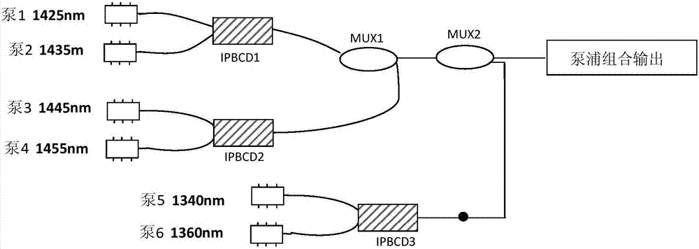
[0044] Figure 1aA second-order Raman amplifier shown requires six coherent light sources as pump sources, including four first-order Raman pump sources with wavelengths of 1425nm, 1435nm, 1445nm, and 1455nm; the second-order Raman pump sources are 2, the wavelengths are 1340nm and 1360nm respectively; Figure 1a IPBCD1 and IPBCD2 are isolated polarization pump combiners, and MUX1 and MUX2 are broadband combiners;

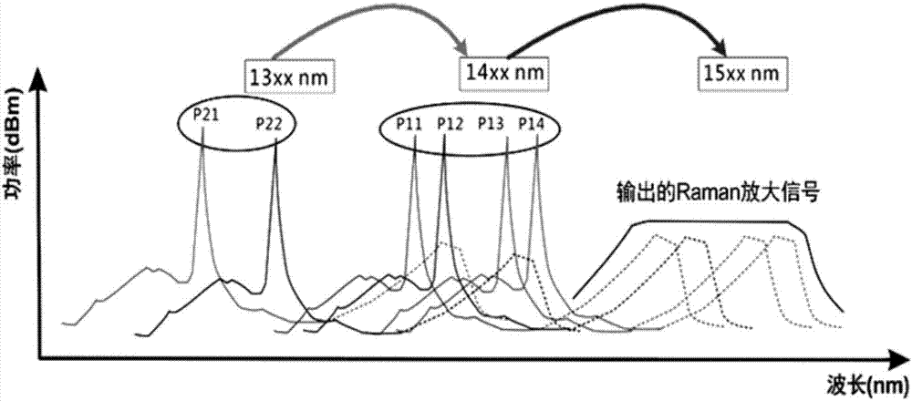
[0045] The principle of high-order Raman pump frequency shift is to use high-power short-wavelength pump light to transfer power to long-wavelength pump light through the gain fiber, and then use long-wavelength pump light to pump signal light; The principle of Raman pump frequency shift is as follows Figure 1b As shown, the signal light spectrum with a wavelength of 15xx nanometers is located at the second-order Raman frequency shift of the pump ...


PUM


Abstract

The invention provides a combined Raman pump source, and the pump source comprises one or more first-order Raman pump sources, one or more second-order Raman pump sources, ...,one or more N-th-order Raman pump sources, and one broadband combiner, wherein N is not less than two. The output end of each Raman pump source is connected with the corresponding input end of the broadband combiner. The first-order Raman pump sources employ incoherent broadband light sources, and the second-order Raman pump sources employ coherent broadband light sources. The frequency spectrum of input signal light is located at the N-th-order Raman frequency shift part of the N-th-order coherent laser light source spectrum, wherein N is not less than two. Meanwhile, the frequency spectrum of input signal light is located at the first-order Raman frequency shift part of the first-order incoherent broadband light source spectrum. The combined Raman pump source can achieve the flat-bandwidth and high-gain spectrum through at least two light sources, reduces the cost, is suitable for the Raman amplifiers of various pumping types, and is especially suitable for the Raman amplifiers of forwarding pumping types.

Description

technical field [0001] The invention relates to an optical transmission device, in particular to a Raman pumping source. Background technique [0002] Raman amplifiers have been used more and more widely in recent years. Raman amplifier is an optical amplifier realized by using the phenomenon of stimulated Raman scattering. A high-power pump light and a low-power signal light are introduced into the same transmission fiber, and the energy from the high-power pump light is transferred to the low-power signal light, thus completing the amplification of the signal light; In a typical case, the wavelength of the high-power pump light is smaller than the wavelength of the low-power signal light, and the difference between the two is designed to be approximately equal to the Stokes transfer of the transmission medium; the pump light and the input signal light can be transmitted in the same direction Or the reverse transmission structure enters the transmission fiber, which corre...

Claims


Application Information

Patent Timeline
Patent Type & Authority Applications(China)
IPC IPC(8): H01S3/0915H01S3/094
CPCH01S3/0915H01S3/094046H01S3/094096
Inventor 迟荣华李现勤
Owner WUXI TACLINK OPTOELECTRONICS TECH CO LTD
Why Eureka
Try Eureka