An automatic fast pyrography device

A fast, pyrograph technology, applied in decorative arts, processes used to produce decorative surface effects, etc., can solve the problems of difficult control of down pressure, reduced hydraulic oil service life, no protective devices, etc., to improve the scope of application, The effect of improving yield, improving stability and uniformity of force

Active Publication Date: 2019-10-15
NANYANG INST OF TECH
View PDF8 Cites 0 Cited by
  • Summary
  • Abstract
  • Description
  • Claims
  • Application Information

AI Technical Summary

Problems solved by technology

However, the traditional "fast pyrographer" has the following problems: (1) The pressing power is still human, which belongs to semi-automatic equipment, and cannot continue to work for a long time; (3) The area of ​​the heating device is not variable, resulting in a waste of resources for the printing material; (4) Difficulty in positioning the feeding material, which affects the product yield and production efficiency
The disadvantage of this structure is that the printing plate is pressed by the hydraulic component, and the strength and accuracy of the pressing process are not easy to control, and the heating plate is installed next to the hydraulic component, which will reduce the service life of the hydraulic oil
[0005] Authorized notification number CN101767506 B discloses a fast pyrographer, which has a workbench, on which a mold steel plate and a screw rod are arranged; Flexible connection; the other end of the lifting arm is pierced with a pressure rod, and the pressure rod is movably connected with the lifting arm through a fine-tuning fixed handle; a pressure steel plate is arranged at the lower end of the pressure rod, and a wooden board is embedded in the bottom of the pressure steel plate; because it adopts manual operation, its downforce is difficult to control

Method used


Image

  • An automatic fast pyrography device
  • An automatic fast pyrography device
  • An automatic fast pyrography device

Examples


Embodiment 1

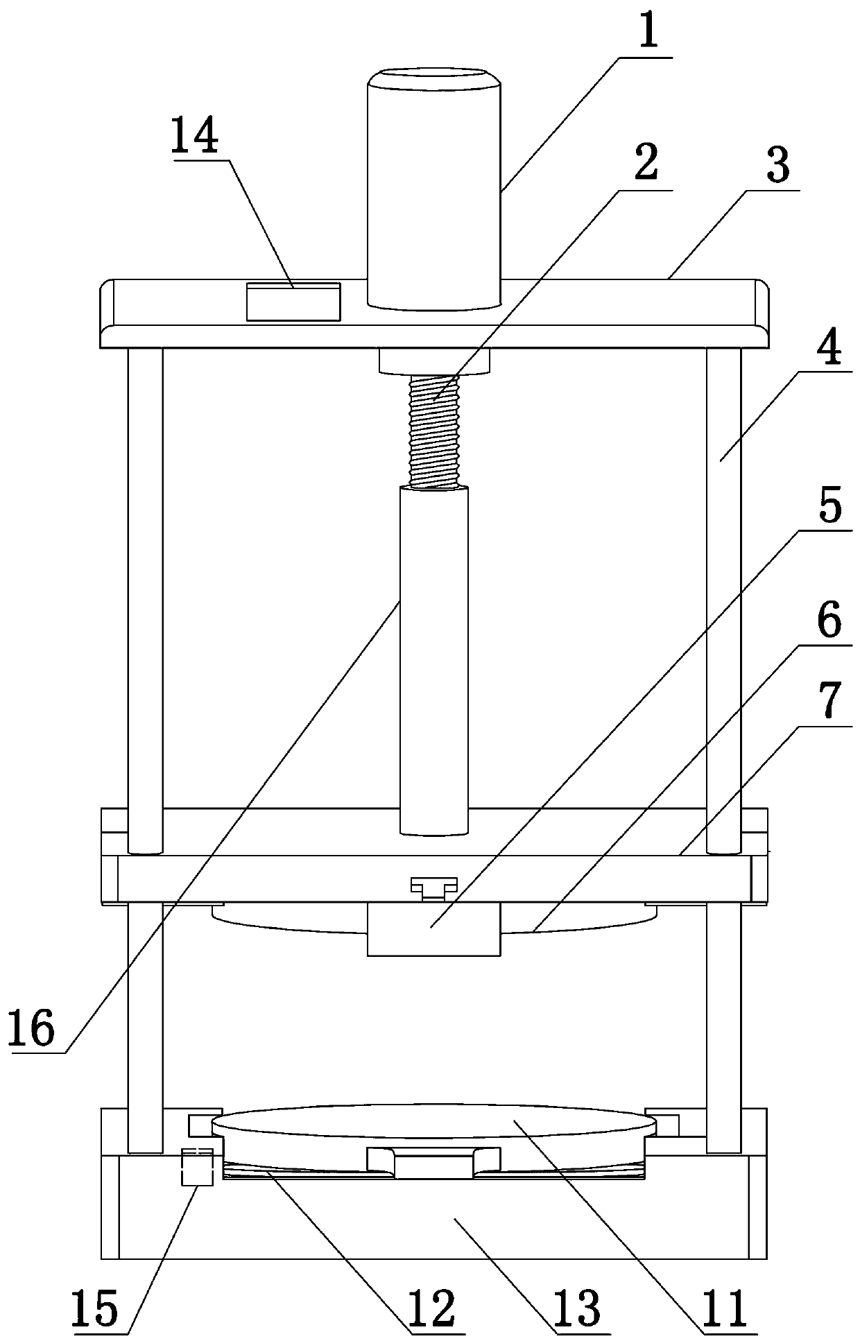
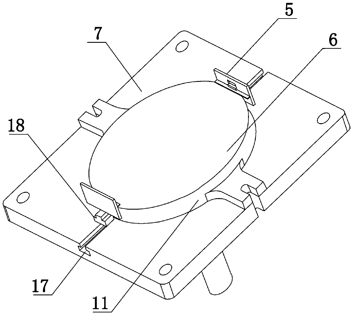
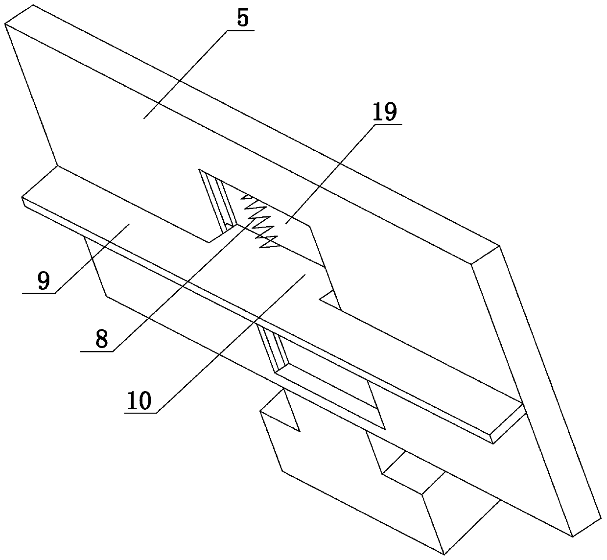
[0033] Such as Figure 1 to Figure 3 As shown, the present invention comprises a base 13, a fixed platen 7, an upper support plate 3, a drive motor 1 and a PLC controller 14, the drive motor 1 adopts a stepper motor, the first output of the PLC controller 14 is connected to the input of the drive motor 1 The terminals are electrically connected, the PLC controller 14 controls the speed, rotation time and forward and reverse direction of the drive motor 1, the base 13 adopts a cuboid structure, the upper end surface of the base 13 is provided with a receiving tank, and the bottom wall and the side wall of the receiving tank are provided with heat insulation layers (not shown in the figure), the heat insulation layer is made of glass wool, and the electric furnace plate 12, the lower template 11 and the temperature controller 15 are arranged in the storage tank, and the output end of the temperature controller 15 is electrically connected with the input end of the PLC controller ...

Embodiment 2

[0038] The structure of this embodiment is basically the same as that of Embodiment 1, the difference is: as Figure 4 As shown, the lower end surface of the fixed platen 7 also offers a T-shaped positioning groove 20, and there are two T-shaped positioning grooves 20, wherein a positioning plate 21 is arranged in one of the T-shaped positioning grooves 20, and an ejector is arranged in the other T-shaped positioning groove 20. , The ejector includes a fixedly connected T-shaped block 22 and a push rod 23, and the T-shaped block 22 is slidably disposed in the T-shaped positioning groove 20.

Embodiment 3

[0040] The structure of this embodiment is basically the same as that of Embodiment 2, the difference is: as Figure 5 As shown, the lower end surface of the fixed platen 7 also offers a T-shaped positioning groove 20, and there are two T-shaped positioning grooves 20, wherein a positioning plate 21 is arranged in one of the T-shaped positioning grooves 20, and an ejector is arranged in the other T-shaped positioning groove 20. , the ejector includes a T-shaped block 22 and a push rod 23, the T-shaped block 22 is slidably arranged in the T-shaped positioning groove 20, and the side end surface of the fixed pressure plate 7 is close to the position of the propeller and the limit baffle 24 is fixedly installed. Open a third through hole (not shown in the figure), the inner end of the push rod 23 runs through the third through hole and is fixedly connected with the T-shaped block 22, and a reset is set between the front end of the limit baffle 24 and the outer end of the push rod ...


PUM


Abstract

The invention belongs to the technical field of art equipment, and particularly relates to an automatic and quick pyrographing device. The device comprises a base, a fixed pressing plate, an upper support plate and a driving motor, wherein an accommodating groove is formed in the upper end surface of the base; an electric furnace disc and a lower template are arranged in the accommodating groove; the electric furnace disc is positioned under the lower template; a plurality of guiding columns in the vertical direction are arranged on the upper end surface of the base; the guiding columns are positioned on the outer side of the accommodating groove; a plurality of first through holes are formed in the fixed pressing plate; the fixed pressing plate is connected with the plurality of guiding columns by the first through holes in a sliding manner; an inner threaded sleeve is arranged on the upper end surface of the fixed pressing plate; a lead screw is connected to the inner part of the inner threaded sleeve by threads; an upper template is arranged on the lower end surface of the fixed pressing plate; a second through hole is formed in the center of the upper support plate; the driving motor is fixed on the upper end surface of the upper support plate; an output shaft of the driving motor is connected with the upper end of the lead screw. By mutual cooperation of the driving motor, the guiding columns and a lead screw driving assembly, the down-press precision degree of the fixed pressing plate can be effectively guaranteed, and the down-press strength is effectively controlled.

Description

technical field [0001] The invention belongs to the technical field of art equipment, in particular to an automatic fast pyrography device. Background technique [0002] Pyrography, also known as heat transfer and fire brush painting, is a treasure of traditional Chinese art. It uses a hot soldering iron to iron out burnt marks on objects for painting. While grasping the temperature and strength of pyrograph creation, it pays attention to "the intention is first, and the pen is shaped". Pyrography not only has the methods of sketching, drawing, pointing, dyeing, rubbing, and line drawing in Chinese painting, but also can produce rich layers and tones, with a strong three-dimensional effect, which resembles brown sketches and lithographs. The national style of traditional painting can also achieve the rigorous realistic effect of Western painting. It has a unique artistic charm, thus giving people a simple and elegant artistic enjoyment with endless aftertaste. [0003] As...

Claims


Application Information

Patent Timeline
Patent Type & Authority Patents(China)
IPC IPC(8): B44C1/02
Inventor 李国慧李东如郑冬田青云贾思雨陈闽任立民杨样冯庆东
Owner NANYANG INST OF TECH
Why Eureka
Try Eureka