Automatic and quick pyrographing device
A fast, pyrograph technology, applied in decorative arts, processes used to produce decorative surface effects, etc., can solve the problems of difficult control of down pressure, reduced hydraulic oil service life, no protective devices, etc., to improve the scope of application, The effect of improving yield, improving stability and uniformity of force
- Summary
- Abstract
- Description
- Claims
- Application Information
AI Technical Summary
Problems solved by technology
Method used
Image
Examples
Embodiment 1
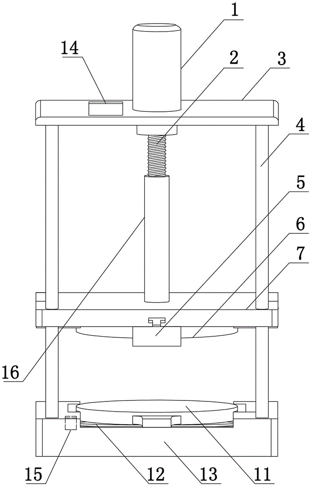
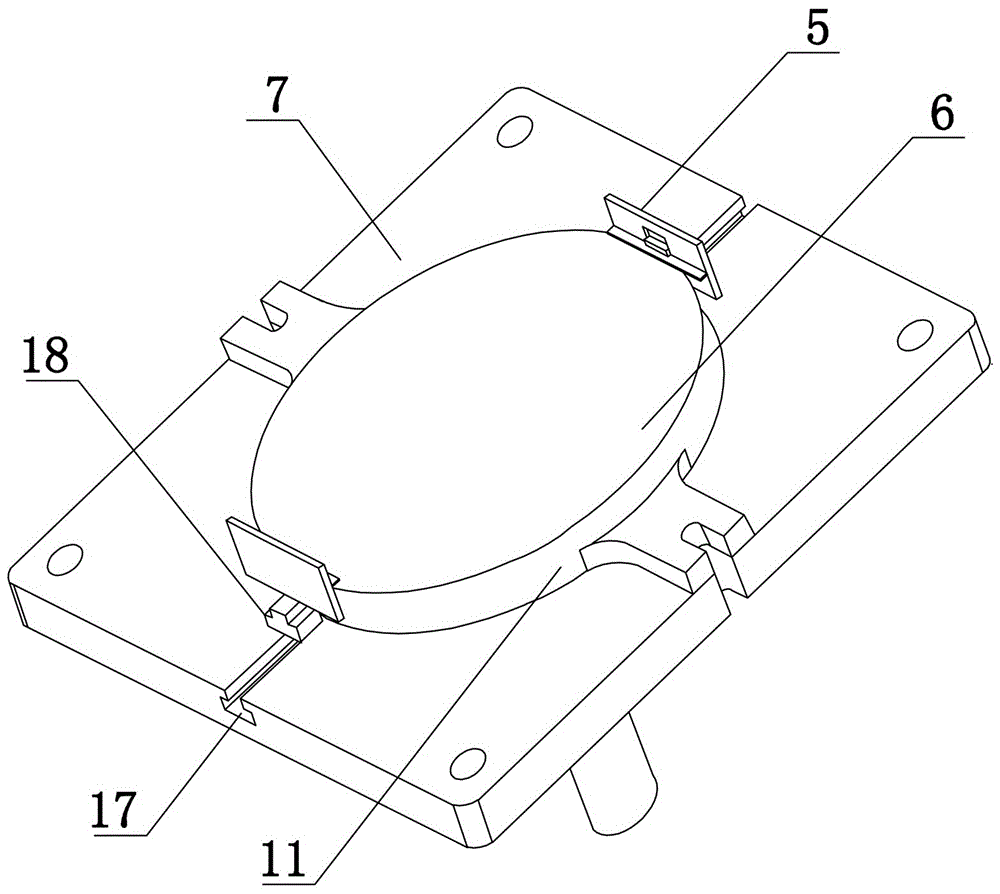
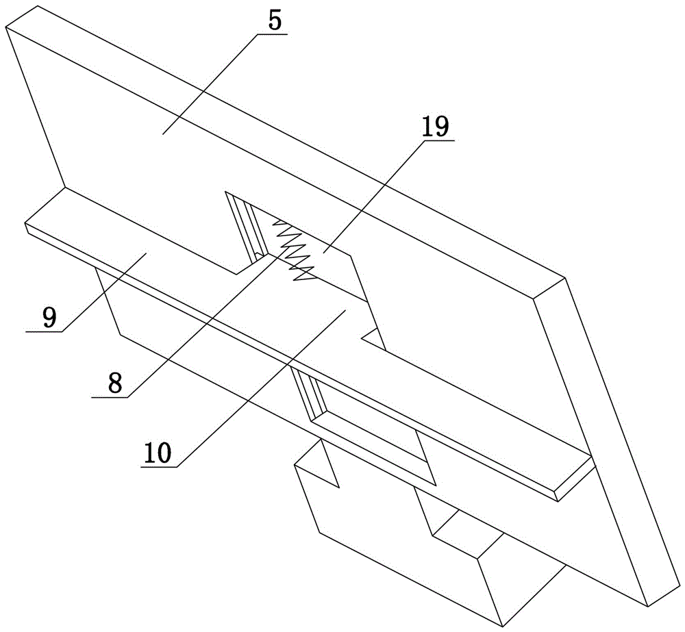
[0033] Such as Figure 1 to Figure 3 As shown, the present invention comprises a base 13, a fixed platen 7, an upper support plate 3, a drive motor 1 and a PLC controller 14, the drive motor 1 adopts a stepper motor, the first output of the PLC controller 14 is connected to the input of the drive motor 1 The terminals are electrically connected, and the PLC controller 14 controls the speed, rotation time and forward and reverse direction of the driving motor 1. The base 13 adopts a cuboid structure, and the upper end surface of the base 13 is provided with a receiving tank, and the bottom wall and the side wall of the receiving tank are provided with heat insulation layers. (not shown in the figure), the heat insulation layer is made of glass wool, and the electric furnace plate 12, the lower template 11 and the temperature controller 15 are arranged in the storage tank, and the output end of the temperature controller 15 is electrically connected with the input end of the PLC ...
Embodiment 2
[0038] The structure of this embodiment is basically the same as that of Embodiment 1, the difference is: as Figure 4 As shown, the lower end surface of the fixed platen 7 also offers a T-shaped positioning groove 20, and there are two T-shaped positioning grooves 20, wherein a positioning plate 21 is arranged in one of the T-shaped positioning grooves 20, and an ejector is arranged in the other T-shaped positioning groove 20. , The ejector includes a fixedly connected T-shaped block 22 and a push rod 23, and the T-shaped block 22 is slidably disposed in the T-shaped positioning groove 20.
Embodiment 3
[0040] The structure of this embodiment is basically the same as that of Embodiment 2, the difference is: as Figure 5 As shown, the lower end surface of the fixed platen 7 also offers a T-shaped positioning groove 20, and there are two T-shaped positioning grooves 20, wherein a positioning plate 21 is arranged in one of the T-shaped positioning grooves 20, and an ejector is arranged in the other T-shaped positioning groove 20. , the ejector includes a T-shaped block 22 and a push rod 23, the T-shaped block 22 is slidably arranged in the T-shaped positioning groove 20, and the side end surface of the fixed pressure plate 7 is close to the position of the propeller and the limit baffle 24 is fixedly installed. Open a third through hole (not shown in the figure), the inner end of the push rod 23 runs through the third through hole and is fixedly connected with the T-shaped block 22, and a reset is set between the front end of the limit baffle 24 and the outer end of the push rod ...
PUM
 Abstract
Description
Claims
Application Information
 - R&D
- Intellectual Property
- Life Sciences
- Materials
- Tech Scout
- Unparalleled Data Quality
- Higher Quality Content
- 60% Fewer Hallucinations
Browse by: Latest US Patents, China's latest patents, Technical Efficacy Thesaurus, Application Domain, Technology Topic, Popular Technical Reports.
© 2025 PatSnap. All rights reserved.Legal|Privacy policy|Modern Slavery Act Transparency Statement|Sitemap|About US| Contact US: help@patsnap.com


