
Micro-strip annular hairpin band-pass filter

A band-pass filter and ring-shaped technology, which is applied in the direction of waveguide devices, resonators, electrical components, etc., can solve the problems of large design space and insufficient compact structure, and achieve the effect of small size, saving design space, and compact and beautiful structure

Inactive Publication Date: 2017-09-19
THE 41ST INST OF CHINA ELECTRONICS TECH GRP
View PDF7 Cites 5 Cited by
  • Summary
  • Abstract
  • Description
  • Claims
  • Application Information

AI Technical Summary

Problems solved by technology

[0007] The present invention proposes a microstrip annular hairpin bandpass filter, through T-shaped tap high-pass filter technology and fan-shaped half-wavelength coupling resonance technology, the ring-shaped half-wavelength coupling resonance of the filter is realized, and the structure of the prior art is solved. Technical issues of compactness and large design space

Method used


Image

  • Micro-strip annular hairpin band-pass filter
  • Micro-strip annular hairpin band-pass filter
  • Micro-strip annular hairpin band-pass filter

Examples


Embodiment 1

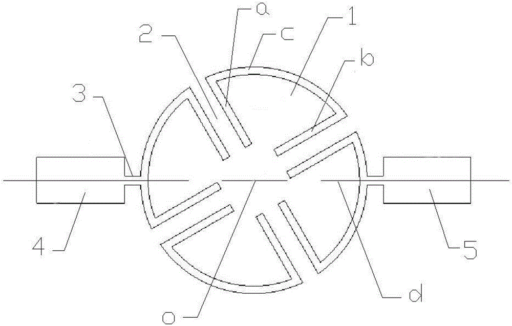
[0024] like figure 2 As shown, the microstrip annular hairpin type bandpass filter of this embodiment includes four identical resonators 1 arranged in a ring around a center o, and the four resonators 1 in this embodiment are arranged in a ring , the two straight segments a, b and a segment c of each resonator 1 form a non-closed sector ring, the four sector rings form a quadrant, and the sector angle of the sector ring formed by each resonator 1 is 90°.

[0025] Each resonator 1 includes two straight sections a, b and a connecting section c connected to the tails of the two straight sections a, b. The heads of the two straight sections a and b form an opening toward the center of the circle o. The coupling between the adjacent resonators 1 is realized through the coupling slot 2; on the two resonators 1 that are oppositely arranged along a certain center line d passing through the center of the circle o, the input port 4 and the output port are respectively connected with t...

Embodiment 2

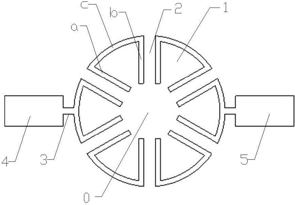
[0030] As shown in Figure 3, the microstrip annular hairpin type bandpass filter of the present embodiment is different from the embodiment 1 in that the number of identical resonators 1 arranged in a ring around a circle center o in the present embodiment There are six resonators 1 in this embodiment, and the six resonators 1 are arranged in a circular shape. The two straight line segments a and b of each resonator 1 and a segment of connecting segment c form a non-closed sector ring, and the six sector rings are composed of Six equal circles are formed, and the sector angle of the sector ring formed by each resonator 1 is 60°.

Embodiment 3

[0032] like Figure 4 As shown, the difference between the microstrip annular hairpin bandpass filter of this embodiment and Embodiment 1 is that the four resonators 1 in this embodiment in this embodiment are arranged in a square ring, and each resonator 1 is arranged in a square ring. The two straight segments a and b of 1 and the connecting segment c form a non-closed triangular ring, and the four triangular rings form a regular quadrilateral divided into quarters. The angle between the two straight segments a and b of each resonator 1 is 90°.


PUM


Abstract

The invention relates to the technical field of microwave engineering and, specifically, relates to a novel micro-strip annular hairpin band-pass filter, which includes a plurality of same resonators arranged annularly around the center of a circle. Each resonator includes two linear segments and a connecting segment connected at tail portions of the two linear segments, and head portions of the two linear segments form an opening facing towards the center of the circle. The adjacent resonators are coupled through coupling gaps. Input and output ports are connected through T-junction taps respectively onto the two resonators arranged relatively along a centerline through the center of the circle. According to the invention, the annular half-wavelength coupling resonance of the filter is realized by means of the T-junction tap high-pass filtering technology and the fan-shaped half-wavelength coupling resonant technology.

Description

technical field [0001] The invention relates to the technical field of microwave engineering, in particular to a novel microstrip annular hairpin bandpass filter. Background technique [0002] The microwave band-pass filter is one of the important microwave devices in microwave engineering. It often appears in the form of a two-port network in the system and completes a basic function, that is, it allows the transmission of microwave signals in the frequency band within the pass band and prevents microwave signals in the stop band band. transmission. This separation and combination of frequencies is also a central issue in the design of most microwave systems. In general, the filters in the RF circuit design are implemented using passive circuits. [0003] With the rapid development of modern communication technology, people need specific frequency bands for mobile communication, so the selection of frequency is particularly important, and it is precisely the filter that c...

Claims


Application Information

Patent Timeline
Patent Type & Authority Applications(China)
IPC IPC(8): H01P1/203H01P7/08
CPCH01P1/20372H01P7/082
Inventor 孙国泉宁曰民刘金现张文强
Owner THE 41ST INST OF CHINA ELECTRONICS TECH GRP
Learn More