
Early warning and fire control system for energy storage power station

A technology of fire protection system and energy storage power station, which is applied in the direction of electric energy storage system, electrical components, fire rescue, etc. It can solve the problems of undetectable or slow detection, insufficient accuracy, limited dosage of fire extinguishing agent, etc., to reduce property Loss, fire control, and the effect of improving monitoring accuracy

Inactive Publication Date: 2017-09-22
YANTAI INNOVATIVE NEW ENERGY TECH CO LTD
View PDF6 Cites 38 Cited by
  • Summary
  • Abstract
  • Description
  • Claims
  • Application Information

AI Technical Summary

Problems solved by technology

[0004] In the existing technology, the overall monitoring of the energy storage cabinet is not accurate enough. When the thermal runaway of a single battery occurs, it may not be detected or the detection may be slow. When a fire is detected, the entire energy storage station space The fire extinguishing agent cannot be used to extinguish the fire in the battery cabinet, and the fire extinguishing effect on the battery is not obvious, so it cannot quickly, effectively and safely extinguish the fire source
In addition, because battery thermal runaway is a chain reaction, battery fires are easy to re-ignite. Traditional fire extinguishing methods can only temporarily suppress the spread of battery thermal runaway due to the limited dosage of fire extinguishing agents, and suppress the fire for a short time. Once the battery re-ignites, it will cause great danger and property. loss
And the fire extinguishing agent is stored for a long time and is prone to failure, so it needs to be replaced regularly

Method used


Image

  • Early warning and fire control system for energy storage power station

Examples


Embodiment 1

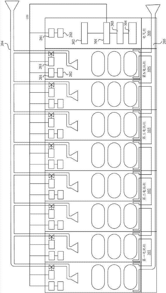
[0057] Embodiment 1: The battery cabinets in the energy storage power station are arranged and layered, and each minimum storage space is a minimum protection unit. A failed battery is not affected. A battery pack is placed in each minimum protection unit, and the battery pack is a closed battery pack structure that meets the requirements of the waterproof level. Regardless of whether there are detectors in the battery pack, detectors and fire extinguishing devices are installed in the smallest protective unit. The upper part of each minimum protection unit is equipped with a solenoid valve activation device. The water inlet pipe is arranged above the battery cabinet and extends to each minimum protection unit. A fire solenoid valve and a sprinkler are installed at the end of the water inlet. The sprinkler is set on the top and side of the battery pack. A water storage tank is installed at the bottom of the protection unit, and the opening of the water storage tank is connect...

Embodiment 2

[0059] Embodiment 2: The storage space of each column of the battery cabinet in the energy storage power station is used as a minimum protection unit. The storage space between each column is a closed structure to reduce the number of batteries affected by high-pressure water mist spraying. A bracket is installed between each layer. The battery pack is an open battery pack structure and placed on the bracket of each protection unit. The detector, fire extinguishing device, and solenoid valve starting device are installed on the top of the minimum protection unit. The water inlet pipe is arranged above the battery cabinet and extends to the upper part and the side of the battery pack. Fire solenoid valves and sprinklers are installed at the end of the minimum protection unit. It is equipped with a water tank and an outlet pipe. When the detector detects a fire, it will control the fire extinguishing device to start and send an early warning signal. After receiving the signal, t...

Embodiment 3

[0060] Embodiment 3: The battery cabinet in the energy storage power station is a layered structure, with a relatively airtight structure between each layer, and each layer of airtight space serves as a minimum protection unit. Multiple battery packs are placed in each minimum protection unit, and the battery pack is an open battery pack structure. The detector, fire extinguishing device, and solenoid valve starting device are installed on the top of the minimum protection unit. The water inlet pipe is arranged above the battery cabinet and extends to the upper part and the side of the battery pack. Fire solenoid valves and sprinklers are installed at the end of the minimum protection unit. It is equipped with a water tank and an outlet pipe. The energy storage power station is connected to the fire water source for a long time. When the detector detects a fire, it controls the start of the fire extinguishing device and sends an early warning signal. After the data concentrat...


PUM


Abstract

The invention discloses an early warning and fire control system for an energy storage power station. A battery cabinet and an electric cabinet are arranged in the energy storage power station; a smallest protection unit is arranged in the battery cabinet and a battery group is internally arranged in the battery cabinet; electric equipment is mounted in the electric cabinet; the early warning and fire control system comprises a safety early warning system and a fire control system; the fire control system is arranged in the smallest protection unit. The fire control system comprises a probe, a fire extinguishing device, a solenoid valve starting device, a water inlet pipeline and a water outlet pipeline; the probe is arranged on the top of the smallest protection unit and is connected with the fire extinguishing device; the solenoid valve starting device is arranged on the top of the smallest protection unit and is electrically connected with a solenoid valve mounted on the water inlet pipeline; the solenoid valve starting device starts, the water inlet pipeline drains the water to the smallest protection unit; the water outlet pipe is arranged at the bottom of the smallest protection unit and the battery cabinet, and water is drained after fire is extinguished; an early warning system is arranged in the electric cabinet, and the early warning system comprises a data concentrator and a BMS host which are mutually connected; the data concentrator is connected with the probe and the solenoid valve starting device; and the BMS host is connected with the data concentrator.

Description

technical field [0001] The invention relates to the technical field of energy storage power stations, in particular to an early warning and fire protection system for energy storage power stations. Background technique [0002] As a new energy battery, lithium-ion batteries are not only more environmentally friendly but also have superior performance, and are widely used in energy storage power stations. However, during the storage process, lithium-ion batteries may experience thermal runaway due to the accumulation of heat generated by their own chemical reactions or the influence of external heat sources, which seriously affects the safety performance of energy storage power stations. [0003] At present, the early warning and fire protection of the energy storage power station are mainly realized through the following methods: multiple different types of fire detectors (temperature-sensing, smoke-sensing or smoke-temperature-integrated) are installed on the top of the ene...

Claims


Application Information

Patent Timeline
IPC IPC(8): A62C3/16A62C37/00H02J15/00
CPCA62C3/16A62C37/00H02J15/00
Inventor 张立磊
Owner YANTAI INNOVATIVE NEW ENERGY TECH CO LTD
Learn More