Surface gluing equipment for machining resistance elements

A resistance element and equipment technology, which is applied in the field of surface coating equipment for resistance element processing, and can solve problems such as low efficiency and uneven coating

Inactive Publication Date: 2017-09-22
周福明
View PDF12 Cites 21 Cited by
  • Summary
  • Abstract
  • Description
  • Claims
  • Application Information

AI Technical Summary

Problems solved by technology

[0005] In order to overcome the shortcomings of low efficiency and uneven coating of manual gluing, the technical problem to be solved by the present invention is to provide a surface gluing equipment for resistive element processing with high efficiency and uniform coating

Method used


Image

  • Surface gluing equipment for machining resistance elements
  • Surface gluing equipment for machining resistance elements
  • Surface gluing equipment for machining resistance elements

Examples


Embodiment 1

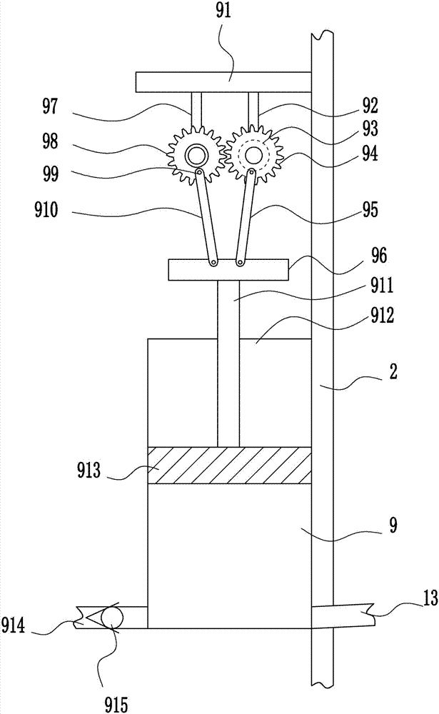
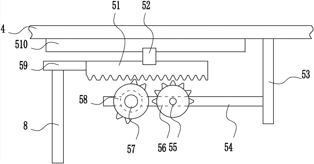
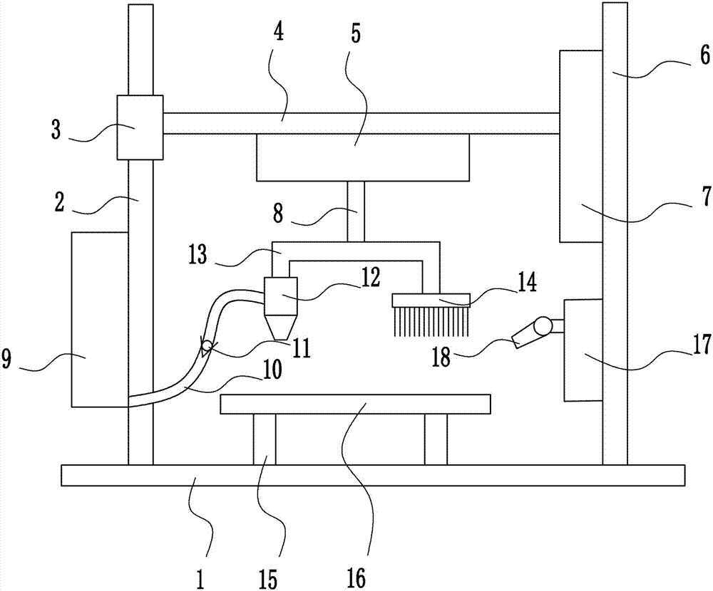
[0036] A surface coating equipment for resistance element processing, such as Figure 1-6 As shown, it includes base plate 1, first guide rod 2, first guide sleeve 3, lifting rod 4, moving device 5, right frame 6, lifting device 7, moving rod 8, glue delivery device 9, hose 10, the first A one-way valve 11, dispensing head 12, T-shaped mounting plate 13, brush 14, first support 15, placement table 16, swing device 17 and fan 18, the first guide rod 2 is welded on the left side of the bottom plate 1 top, the second A guide rod 2 is sleeved with a first guide sleeve 3, a right frame 6 is welded on the right side of the top of the bottom plate 1, a moving device 5 is arranged on the upper left side of the right frame 6, and a lifting rod 4 is connected to the left side of the moving device 5, and the lifting rod 4. The left end is connected to the right end of the first guide sleeve 3 by welding. A moving device 5 is arranged in the middle of the bottom of the lifting rod 4. The ...

Embodiment 2

[0038] A surface coating equipment for resistance element processing, such as Figure 1-6 As shown, it includes base plate 1, first guide rod 2, first guide sleeve 3, lifting rod 4, moving device 5, right frame 6, lifting device 7, moving rod 8, glue delivery device 9, hose 10, the first A one-way valve 11, dispensing head 12, T-shaped mounting plate 13, brush 14, first support 15, placement table 16, swing device 17 and fan 18, the first guide rod 2 is welded on the left side of the bottom plate 1 top, the second A guide rod 2 is sleeved with a first guide sleeve 3, a right frame 6 is welded on the right side of the top of the bottom plate 1, a moving device 5 is arranged on the upper left side of the right frame 6, and a lifting rod 4 is connected to the left side of the moving device 5, and the lifting rod 4. The left end is connected to the right end of the first guide sleeve 3 by welding. A moving device 5 is arranged in the middle of the bottom of the lifting rod 4. The ...

Embodiment 3

[0041] A surface coating equipment for resistance element processing, such as Figure 1-6As shown, it includes base plate 1, first guide rod 2, first guide sleeve 3, lifting rod 4, moving device 5, right frame 6, lifting device 7, moving rod 8, glue delivery device 9, hose 10, the first A one-way valve 11, dispensing head 12, T-shaped mounting plate 13, brush 14, first support 15, placement table 16, swing device 17 and fan 18, the first guide rod 2 is welded on the left side of the bottom plate 1 top, the second A guide rod 2 is sleeved with a first guide sleeve 3, a right frame 6 is welded on the right side of the top of the bottom plate 1, a moving device 5 is arranged on the upper left side of the right frame 6, and a lifting rod 4 is connected to the left side of the moving device 5, and the lifting rod 4. The left end is connected to the right end of the first guide sleeve 3 by welding. A moving device 5 is arranged in the middle of the bottom of the lifting rod 4. The b...


PUM


Abstract

The invention relates to gluing equipment, in particular to surface gluing equipment for machining resistance elements. The surface gluing equipment for machining the resistance elements is high in efficiency and uniform in coating. The surface gluing equipment for machining the resistance elements comprises a bottom plate, a first guiding rod, a first guiding sleeve, a lifting rod, a moving device, a right frame, a lifting device, a moving rod, a glue-conveying device, a flexible pipe, a first one-way valve and the like. The left side of the top of the bottom plate is welded to the first guiding rod. The first guiding rod is connected with the first guiding sleeve in a sleeved mode. The right side of the top of the bottom plate is welded to the right frame. The moving device is arranged above the left side of the right frame. The left side of the moving device is connected with the lifting rod. According to the surface gluing equipment for machining the resistance elements, the height of a solder dispensing tool and a brush is controlled through the lifting device, the surface gluing equipment is more humanized, by cooperative using of the moving device and the glue conveying device, the coating is more uniform, and the effect is better.

Description

technical field [0001] The invention relates to a gluing equipment, in particular to a surface gluing equipment for resistive element processing. Background technique [0002] The resistance value of a resistance element is generally related to temperature, material, length, and cross-sectional area. The physical quantity that measures resistance affected by temperature is the temperature coefficient, which is defined as the percentage change in resistance value when the temperature increases by 1 °C. The main physical feature of a resistor is to convert electrical energy into heat energy. It can also be said that it is an energy-consuming element, and internal energy is generated when current passes through it. Resistors usually act as voltage dividers and shunts in circuits. For signals, both AC and DC signals can pass through resistors. [0003] The processing of electronic components needs to apply glue on the circuit board, so that the resistance components are adhere...

Claims


Application Information

Patent Timeline
Patent Type & Authority Applications(China)
IPC IPC(8): B05C9/12B05C5/02B05C11/02
CPCB05C9/12B05C5/0208B05C11/023
Inventor 不公告发明人
Owner 周福明
Why Eureka
Try Eureka