Laser marking robot

A laser marking and robotic technology, applied in the field of laser marking, can solve the problems of high risk, high operation difficulty, and increased marking operation cost, so as to avoid congestion and blockage, reduce personnel participation, and shorten cycle time Effect

Active Publication Date: 2017-09-22
重庆百钰顺科技有限公司
View PDF6 Cites 3 Cited by
  • Summary
  • Abstract
  • Description
  • Claims
  • Application Information

AI Technical Summary

Problems solved by technology

[0003] At present, during the marking process of traditional laser marking equipment, the products to be marked and the marked products cannot be automatically transported, which greatly limits the efficiency of product marking; at the same time, the existing laser marking robots are When marking the product with the 3D workbench, manual loading and unloading is required, which not only makes the operation difficult and dangerous, but also increases the cost of the marking operation; in addition, the existing 3D workbench can only carry out angle Adjustment and short-range up and down translation, when marking long or high objects, the product needs to be positioned multiple times, which not only affects the continuity and marking accuracy of the marking operation, but also greatly limits Improve the efficiency of marking operations

Method used


Image

  • Laser marking robot
  • Laser marking robot
  • Laser marking robot

Examples


Embodiment

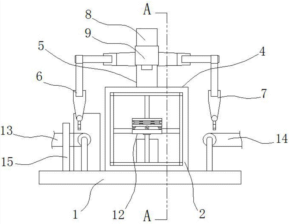
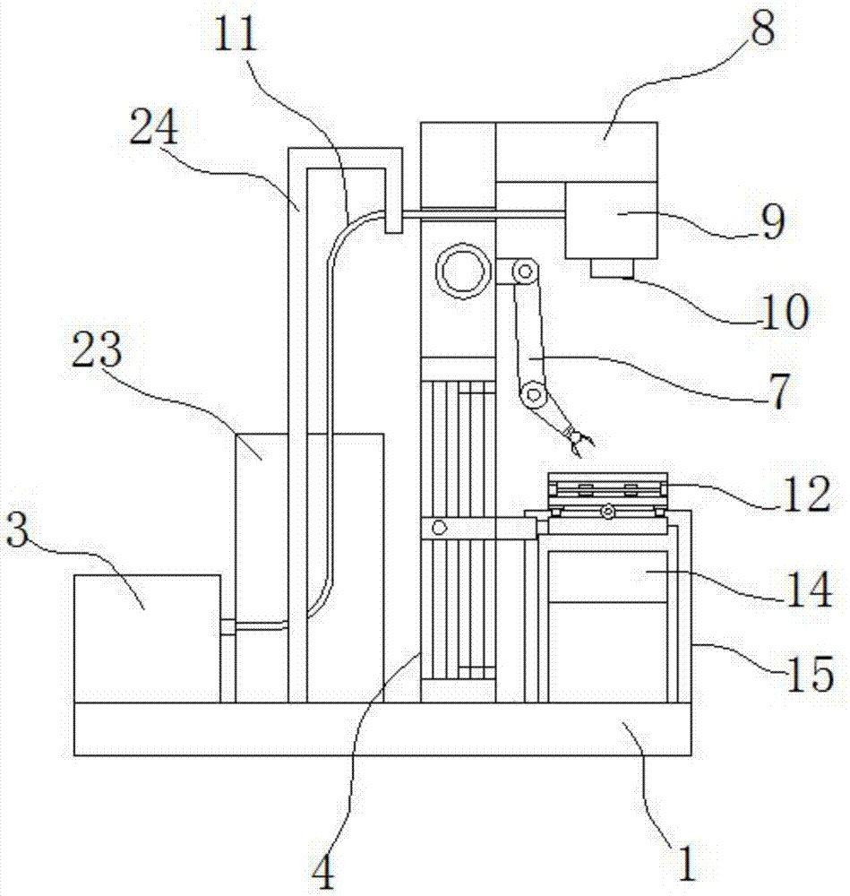
[0022] Such as Figure 1-4 As shown, a laser marking robot includes a base 1. The base 1 is provided with a robot body 2, a control host 23, and an optical fiber marking machine host 3. The robot body 2 includes a three-dimensional translation mechanism 4 connected to the base 1. The three-dimensional translation The upper end of the mechanism 4 is connected with a column 5, the left and right ends of the column 5 are respectively connected with the first mechanical arm 6 and the second mechanical arm 7, the upper front side of the column 5 is connected with a beam 8, and the lower side of the front end of the beam 8 is connected with a The vibrating mirror 9 is connected to the field mirror 10 at the lower end of the vibrating mirror 9, and the vibrating mirror 9 is connected to the host machine 3 of the fiber marking machine through the optical fiber 11. It is worth mentioning that the base 1 is provided with a balance bracket 24 for erecting the optical fiber 11, And a heat...


PUM


Abstract

The invention belongs to the technical field of laser marking, and particularly relates to a laser marking robot. The laser marking robot comprises a base, wherein a robot body, a control host machine and an optical marking machine host machine are arranged on the base; the robot body comprises a three-dimensional translation mechanism connected with the base; the upper end of the three-dimensional translation mechanism is connected with a stand column; the left end and the right end of the stand column are separately connected with a second mechanical arm and a first mechanical arm; the front side of the upper end of the stand column is connected with a beam; the lower side of the front end of the beam is connected with a galvanometer; the lower end of the galvanometer is connected with a field lens; the galvanometer is connected with the optical fiber marking machine host machine through an optical fiber; a three-dimensional workbench is arranged at the lower side of the field lens; the three-dimensional workbench is connected with the three-dimensional translation mechanism; and the second mechanical arm, the first mechanical arm, the optical fiber marking machine host machine and the three-dimensional workbench are electrically connected with the control host machine separately. The laser marking robot has the advantages of effectively shortening the marking period of a single product, improving product marking efficiency, reducing participation of staff and reducing product marking operation cost.

Description

technical field [0001] The invention belongs to the technical field of laser marking, and in particular relates to a laser marking robot. Background technique [0002] With the continuous advancement of science and technology, laser processing technology has developed rapidly. At the same time, laser marking technology is an emerging advanced manufacturing technology in the field of laser processing. Especially in recent years, the rapid development of computer technology, the gradual improvement of optical devices, and the continuous improvement of the reliability and practicability of lasers have all rapidly promoted the development of laser marking technology and further expanded its application prospects in various industries. Laser marking technology is a new type of non-contact, non-polluting and non-damaging marking process. It integrates laser technology, computer technology and mechatronics technology. It is also an advanced manufacturing technology most widely used...

Claims


Application Information

Patent Timeline
IPC IPC(8): B23K26/362B23K26/70
CPCB23K26/361B23K26/702
Inventor 周玉杰
Owner 重庆百钰顺科技有限公司
Why Eureka
Try Eureka