Automatic clamping and fixing device for building pipelines

A fixing device and clamping technology, applied in the direction of positioning device, clamping device, clamping, etc., can solve the problem of inconvenient clamping and fixing of pipelines, and achieve the effects of easy popularization and application, convenient operation and simple overall structure.

Inactive Publication Date: 2017-09-22
CHINA MCC5 GROUP CORP
View PDF9 Cites 12 Cited by
  • Summary
  • Abstract
  • Description
  • Claims
  • Application Information

AI Technical Summary

Problems solved by technology

[0003] The purpose of the present invention is to overcome the deficiencies of the prior art, and the purpose is to provide an automatic clamping and fixing device for construction pipelines to solve the problem of inconvenient clamping and fixing of pipelines

Method used


Image

  • Automatic clamping and fixing device for building pipelines
  • Automatic clamping and fixing device for building pipelines
  • Automatic clamping and fixing device for building pipelines

Examples


Embodiment 1

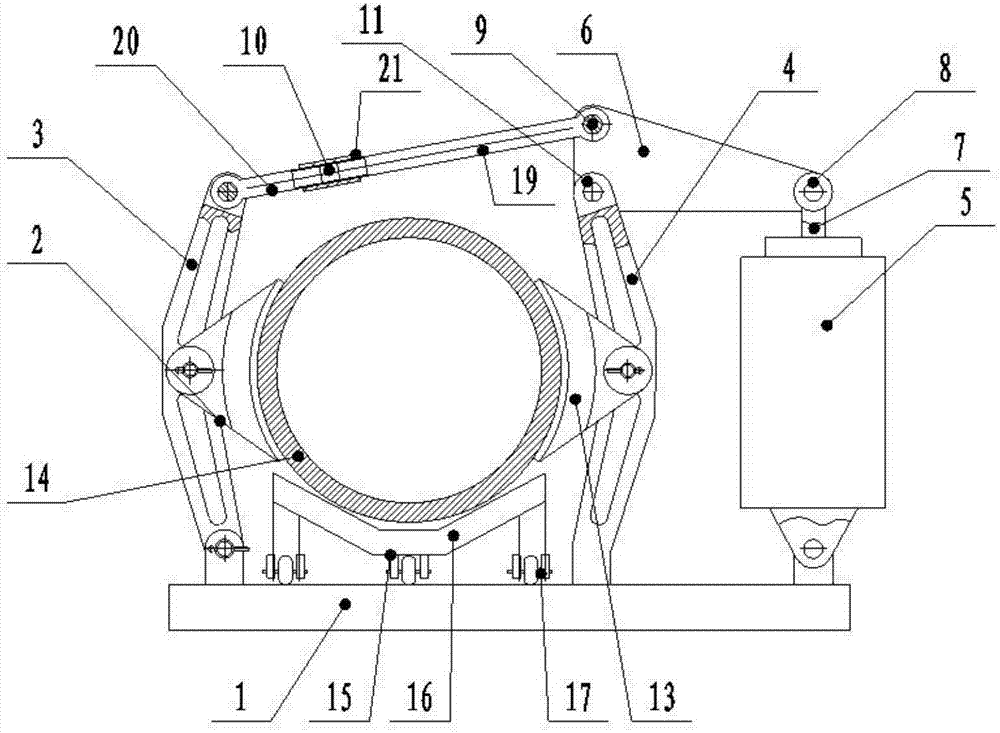
[0025] like figure 1 and 3 As shown, the present invention is an automatic clamping and fixing device for construction pipelines. In this embodiment, the triangular lever 6 is rotated and supported by a support rod 12, which includes a clamping platform 1 and a clamping assembly 2. The clamping platform 1 is evenly distributed. There are multiple sets of clamping components 2, and the number of sets of clamping components 2 depends on the length of the pipeline 14 and the clamping table 1. Generally, the distance between two sets of clamping components 2 is 1m-1.5m. The clamping components 2 include The first clamping arm 3, the second clamping arm 4, the pneumatic pusher 5 and the triangle lever 6, the first clamping arm 3 and the second clamping arm 4 adopt hollow casting, the first clamping arm 3 and the second clamping arm The bottom end of the loading arm 4 is symmetrically hinged on both sides of the clamping table 1, and the outside of the second clamping arm 4 is prov...

Embodiment 2

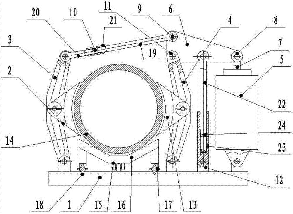
[0031] like figure 2 and 3 As shown, the present invention is an automatic clamping and fixing device for construction pipelines. In this embodiment, the triangular lever 6 is rotated and supported by the second clamping arm 4. Compared with Embodiment 1, the support rod 12 is omitted, and the clamping platform is included. 1 and the clamping assembly 2, multiple sets of clamping assemblies 2 are evenly distributed on the clamping table 1, the number of sets of clamping assemblies 2 depends on the length of the pipeline 14 and the clamping table 1, generally two sets of clamping assemblies 2 The distance between them is 1m-1.5m. The clamping assembly 2 includes a first clamping arm 3, a second clamping arm 4, a pneumatic pusher 5 and a triangular lever 6. The first clamping arm 3 and the second clamping arm 4 adopts hollow casting, the bottom end of the first clamping arm 3 is hingedly installed on the clamping platform 1, and the bottom end of the first clamping arm 4 is fi...


PUM


Abstract

The invention discloses an automatic clamping and fixing device for construction pipelines, which comprises a clamping table and a clamping assembly, and a plurality of sets of clamping assemblies are uniformly arranged on the clamping table, and the clamping assembly includes a first clamping assembly Arm, second clamping arm, pneumatic pusher and triangular lever, the bottom ends of the first clamping arm and the second clamping arm are symmetrically hinged on both sides of the clamping platform, and the outside of the second clamping arm is set There is a pneumatic pusher, the end of the telescopic arm of the pneumatic pusher is hinged with the first angle of the triangular lever, the second angle of the triangular lever is connected with the upper end of the first clamping arm through a connecting rod, the third angle of the triangular lever It is hinged with the upper end of the second clamping arm, and a support rod is provided between the second clamping arm and the pneumatic pusher. The upper end of the support rod is hinged on the triangular lever, and the lower end is hinged on the clamping platform.

Description

technical field [0001] The invention relates to the field of construction engineering, in particular to an automatic clamping and fixing device for construction pipelines. Background technique [0002] In the field of construction or road and bridge engineering construction, it is often necessary to lay pipes. When laying pipelines, it is often necessary to quickly and simply fix the pipelines on iron plates, channel steel or angle irons and other receptors for cutting, drilling or welding operations. At present, splints or welding are generally used for clamping and fixing of pipelines. The fixing method, the above-mentioned fixing structure, is either not fixed firmly, or it is easy to cause damage to the pipeline. For example, the commonly used PVC pipeline is not suitable for welding and fixing, and the ordinary clamping is easy to cause the pipeline to be damaged due to unbalanced force. Contents of the invention [0003] The purpose of the present invention is to ov...

Claims


Application Information

Patent Timeline
Patent Type & Authority Applications(China)
IPC IPC(8): B23Q3/08B23K37/053
CPCB23Q3/08B23K37/0533B23Q2703/04
Inventor 彭德坤保善才尹俊
Owner CHINA MCC5 GROUP CORP
Why Eureka
Try Eureka