
Mixed type movable energy supply equipment

A kind of supply equipment and hybrid technology, applied in the field of hybrid mobile energy supply equipment, can solve the problems of waste of manpower and material resources, troublesome installation and disassembly, and reduce work efficiency, so as to save time and labor, easy to install and disassemble, and improve work efficiency. efficiency effect

Inactive Publication Date: 2017-09-22
ANHUI KOJU ELECTRIC APPLIANCE CO LTD
View PDF0 Cites 4 Cited by
  • Summary
  • Abstract
  • Description
  • Claims
  • Application Information

AI Technical Summary

Problems solved by technology

[0003] The purpose of the present invention is to solve the shortcomings in the prior art, such as: the traditional mobile energy equipment has a complex structure, and due to the complex structure during maintenance, it is particularly troublesome to install and disassemble, and a lot of manpower and material resources are wasted. reduces work efficiency, and proposes a hybrid mobile energy supply device

Method used


Image

  • Mixed type movable energy supply equipment
  • Mixed type movable energy supply equipment

Examples


Embodiment Construction

[0015] The following will clearly and completely describe the technical solutions in the embodiments of the present invention with reference to the accompanying drawings in the embodiments of the present invention. Obviously, the described embodiments are only some, not all, embodiments of the present invention.

[0016] In describing the present invention, it should be understood that the terms "upper", "lower", "front", "rear", "left", "right", "top", "bottom", "inner", " The orientation or positional relationship indicated by "outside", etc. is based on the orientation or positional relationship shown in the drawings, and is only for the convenience of describing the present invention and simplifying the description, rather than indicating or implying that the referred device or element must have a specific orientation, so as to Specific orientation configurations and operations, therefore, are not to be construed as limitations on the invention.

[0017] refer to Figure ...


PUM


Abstract

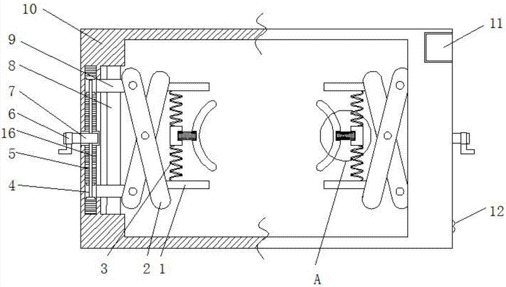
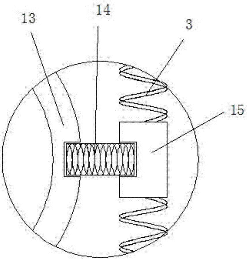
The invention discloses mixed type movable energy supply equipment which comprises a rack. A pulley is arranged at the bottom end of the rack. A rotary shaft is arranged on each side of the rack in a penetrating manner. The end, penetrating the corresponding side wall of the rack, of each rotary shaft is provided with a handle. A coil spring is fixedly connected to each rotary shaft. A gear rack is arranged on one side of each rotary shaft. One side of each gear rack is fixedly connected to the rack. An I-shaped gear is in engaged connection to each gear rack. The other end of each coil spring is connected to the corresponding I-shaped gear in a winding manner. A rolling bearing is connected to each I-shaped gear in a clamped manner. Moving rods are arranged in each rolling bearing in a penetrating manner. A sliding rod is arranged on the moving rods of each rolling bearing in a penetrating manner and connected to the rack in a clamped manner. The equipment is simple in structure and easy to operate; through the interaction of telescopic rods, springs, arc clamp plates and other structures, a movable energy body can be mounted and demounted easily; time and labor force are greatly saved during maintaining; and work efficiency is improved.

Description

technical field [0001] The invention relates to the technical field of mobile energy supply, in particular to a hybrid mobile energy supply device. Background technique [0002] Mobile energy supply equipment can be widely used in construction sites, large gatherings, disaster relief sites, mines, night activities and other places that need to provide temporary power supply at night, which can meet the needs of large-scale and rapid urban construction and enrich people's culture The needs of life, mineral exploration and development, and various industrial construction and social life needs. The structure of traditional mobile energy equipment is complex, and due to the complex structure during maintenance, it is particularly troublesome to install and disassemble, which wastes a lot of manpower and material resources and reduces work efficiency. Contents of the invention [0003] The purpose of the present invention is to solve the shortcomings in the prior art, such as:...

Claims


Application Information

Patent Timeline
Patent Type & Authority Applications(China)
IPC IPC(8): B25H5/00
CPCB25H5/00
Inventor 姚其林顾运辉戚功成
Owner ANHUI KOJU ELECTRIC APPLIANCE CO LTD
Learn More