Printing head for 3D printing

A 3D printing and print head technology, applied in the field of 3D printing, can solve the problems affecting the molding quality of 3D printers and the limited cooling effect, and achieve the effect of rapid and efficient cooling treatment, reducing the impact, and preventing liquid breakage.

Inactive Publication Date: 2017-09-22
ANHUI ORIGINAL POWER PRODUCTIVITY PROMOTION CENT CO LTD
View PDF2 Cites 5 Cited by
  • Summary
  • Abstract
  • Description
  • Claims
  • Application Information

AI Technical Summary

Problems solved by technology

The 3D printer nozzle cooling device overcomes the problem that in the prior art, a cooling fan is usually installed at the nozzle to dissipate heat from the nozzle, but during the printing process, the vibration generated by the operation of the cooling fan will seriously affect the molding quality of the 3D printer.
[0004] This patent only uses one method to cool down the nozzle, so the cooling effect is limited

Method used


Image

  • Printing head for 3D printing
  • Printing head for 3D printing
  • Printing head for 3D printing

Examples


Embodiment 1

[0018] Preferred embodiments of the present invention will be described in detail below in conjunction with the accompanying drawings.

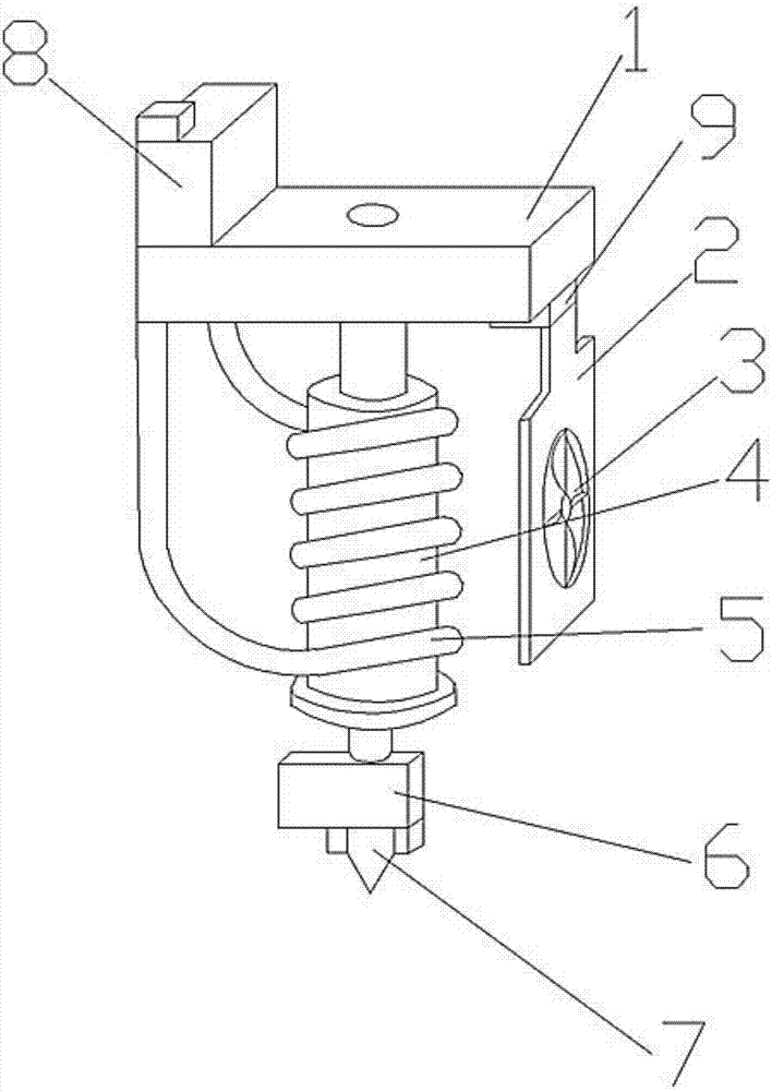
[0019] Figure 1-3 A specific embodiment of the present invention is shown: a printing head for 3D printing, including a mobile platform 1, a fan mounting plate 2, a cooling fan 3, an inkjet bucket 4, a cooling circulation pipe 5, a laser positioner 6, a printing needle 7 and The binomial isolated coolant tank 8, the binomial isolated coolant tank 8 is set and fixed on the mobile platform 1, the ink jet bucket 4 is fixed on the mobile platform 1, the cooling circulation pipe 5 is wound and set on the ink jet bucket 4, and the two ends The connection is set on the binomial isolated coolant tank 8, the fan cooling plate 2 is fixedly set on the mobile platform 1, the heat dissipation fan 3 is set on the fan mounting plate 2, the printing needle 7 is connected and set on the inkjet bucket 4, and the laser positioner 6 is arranged on the printing...

Embodiment 2

[0023] Preferred embodiments of the present invention will be described in detail below in conjunction with the accompanying drawings.

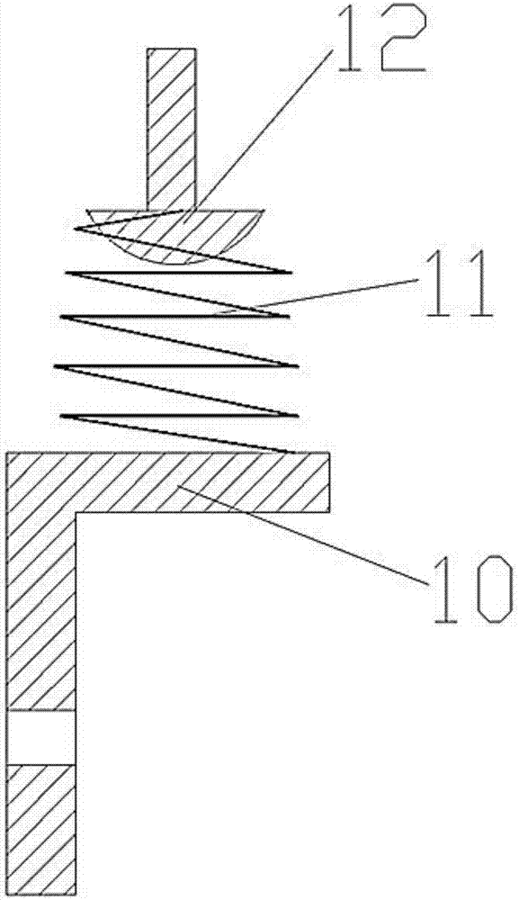
[0024] figure 1 and figure 2 A specific embodiment of the present invention is shown: a printing head for 3D printing, including a mobile platform 1, a fan mounting plate 2, a cooling fan 3, an inkjet bucket 4, a cooling circulation pipe 5, a laser positioner 6, a printing needle 7 and The binomial isolated coolant tank 8, the binomial isolated coolant tank 8 is set and fixed on the mobile platform 1, the ink jet bucket 4 is fixed on the mobile platform 1, the cooling circulation pipe 5 is wound and set on the ink jet bucket 4, and the two ends The connection is set on the binomial isolated coolant tank 8, the fan cooling plate 2 is fixedly set on the mobile platform 1, the heat dissipation fan 3 is set on the fan mounting plate 2, the printing needle 7 is connected and set on the inkjet bucket 4, and the laser positioner 6 is arranged on ...

Embodiment 3

[0027] Preferred embodiments of the present invention will be described in detail below in conjunction with the accompanying drawings.

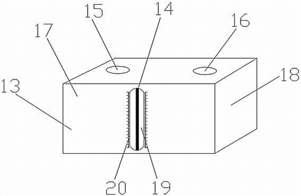
[0028] figure 1 and image 3 A specific embodiment of the present invention is shown: a printing head for 3D printing, including a mobile platform 1, a fan mounting plate 2, a cooling fan 3, an inkjet bucket 4, a cooling circulation pipe 5, a laser positioner 6, a printing needle 7 and The binomial isolated coolant tank 8, the binomial isolated coolant tank 8 is set and fixed on the mobile platform 1, the ink jet bucket 4 is fixed on the mobile platform 1, the cooling circulation pipe 5 is wound and set on the ink jet bucket 4, and the two ends The connection is set on the binomial isolated coolant tank 8, the fan cooling plate 2 is fixedly set on the mobile platform 1, the heat dissipation fan 3 is set on the fan mounting plate 2, the printing needle 7 is connected and set on the inkjet bucket 4, and the laser positioner 6 is arranged on t...


PUM


Abstract

The invention discloses a printing head for 3D printing. The printing head for 3D printing comprises a mobile platform, a fan installation plate, a cooling fan, an inkjet duct, a cooling circulating pipe, a laser locator, a printing needle and a binomial insulation coolant tank which is fixedly arranged on the mobile platform. The inkjet duct is fixedly arranged on the mobile platform. The cooling circulating pipe is wound around the inkjet duct, and the two ends of the cooling circulating pipe are connected to the binomial insulation coolant tank. A fan cooling plate is fixedly arranged on the mobile platform. The cooling fan is arranged on the fan installation plate. The printing needle is connected to the inkjet duct. The laser locator is arranged on the printing needle. According to the printing head for the 3D printing, a coolant device and a fan cooling device are added, and therefore fast and efficient cooling processing can be conducted on inkjet duct for printing efficiently, and inkjet duct aging because of work heat generation is prevented.

Description

technical field [0001] The invention relates to the field of 3D printing, in particular to a printing head for 3D printing. Background technique [0002] As one of the core components of the 3D printer, the nozzle of the 3D printer largely determines the quality of the molding. The smoothness of the filament flowing out of the extrusion nozzle and the temperature of the filament directly affect the accuracy of 3D printing. However, if the temperature of the nozzle is too high, other components will be dissolved and burned, so a heat dissipation device is required to control the temperature of the nozzle within a certain range. At present, the heat dissipation method for the nozzle is relatively simple, so the heat dissipation and cooling efficiency is not high. [0003] For example, patent CN201611049431.2 discloses a 3D printer nozzle cooling device, including: fixed table (1), cooling water pipe (2) and water circulation device (6), the nozzle (3) of 3D printer is vertic...

Claims


Application Information

Patent Timeline
IPC IPC(8): B29C64/20B29C64/209B29C64/112B29C35/16B33Y30/00
CPCB29C35/16B33Y30/00
Inventor 徐忠张学兵
Owner ANHUI ORIGINAL POWER PRODUCTIVITY PROMOTION CENT CO LTD
Why Eureka
Try Eureka