Batch drilling equipment for machining

A technology of machining and drilling equipment, applied in metal processing equipment, drilling/drilling equipment, boring/drilling and other directions, can solve the problem of low processing efficiency, improve processing efficiency, improve anti-skid performance, guarantee The effect of the cooling effect

Pending Publication Date: 2020-12-29
杨晓成
View PDF9 Cites 2 Cited by
  • Summary
  • Abstract
  • Description
  • Claims
  • Application Information

AI Technical Summary

Problems solved by technology

[0003] Drilling of the workpiece is a common mechanical processing method, but most of the traditional mechanical drilling equipment is relatively simple in design. In the actual operation process, it is usually only able to process a single hole. Processing one by one, the overall processing efficiency is not high, so there are certain limitations

Method used


Image

  • Batch drilling equipment for machining
  • Batch drilling equipment for machining
  • Batch drilling equipment for machining

Examples


Embodiment 1

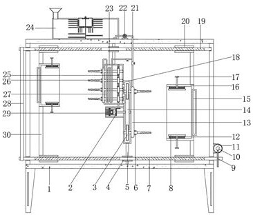
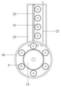
[0030] refer to Figure 1-4 , a batch drilling equipment for mechanical processing, comprising a frame 1 with legs welded at the four corners of the outer wall of the bottom, the inner walls of both ends of the frame 1 are vertically welded with connecting rods 5, and the opposite sides of the connecting rods 5 are respectively The frame box 23 and the tube box 18 are fixed by bolts, and the opposite side of the frame box 23 and the tube box 18 are fixedly connected by bolts, and the outer wall of one side of the tube box 18 is fixed with a rotary motor 29 by bolts, and the rotary motor The output shaft of 29 is key-connected with the drive toothed disc 14, and the edge of the installation cylinder box 18 is connected with the rotating rod one through the bearing rotation, and one end of the rotating rod one is keyed with the driven gear meshed with the driving toothed disc 14 3. The inner wall of the frame box 23 is rotatably connected with a driven worm 25 through bearings, ...

Embodiment 2

[0041] refer to Figure 5 , a batch drilling equipment for mechanical processing, compared with the embodiment 1, this embodiment also includes a butterfly piece 43 welded on one side of the outer wall of the driven gear 3 and the driven worm wheel 31 .

[0042] When the present invention is in use: Utilize the butterfly piece 43 that is arranged on one side of the driven gear 3 and the driven worm wheel 31, during the rotation process of the driven gear 3 and the driven worm wheel 31, it can rotate accordingly, effectively accelerating the frame box 23, Install the air flow inside the cylinder box 18 to achieve the purpose of improving the cooling effect of the curved pipe 27 .


PUM


Abstract

The invention belongs to the technical field of machining, particularly relates to batch drilling equipment for machining, and provides the following scheme for solving the problems that most of drilling equipment in the traditional machining process is simple in design, a single-hole one-by-one machining operation mode is generally adopted, and the machining efficiency is not high. The equipmentcomprises a frame with supporting legs welded to the four corners of the outer wall of the bottom, connecting frame rods are vertically welded to the inner walls of the two ends of the frame, a framebox and a mounting cylinder box are fixed to the opposite sides of the connecting frame rods through bolts correspondingly, and the opposite sides of the frame box and the mounting cylinder box are fixedly connected through bolts; and a rotating motor is fixed to the outer wall of one side of the mounting cylinder box through a bolt, and an output shaft of the rotating motor is in key connection with a driving fluted disc. By means of drilling holes formed in the ends of a first rotating rod and a second rotating rod, rapid drilling of strip-shaped and annularly-distributed holes in a workpiece is facilitated, and the machining efficiency of the device is improved.

Description

technical field [0001] The invention relates to the technical field of machining, in particular to a batch drilling equipment for machining. Background technique [0002] Machining refers to the process of changing the shape or performance of a workpiece through a mechanical device. According to the difference in processing method, it can be divided into cutting processing and pressure processing. In the production process, the process of changing the shape, size, position and nature of the production object to make it a finished or semi-finished product is called a process. It is an essential part of the production process. The process can be divided into casting, forging, stamping, welding, machining, assembly and other processes. The mechanical manufacturing process generally refers to the sum of the machining process of parts and the assembly process of machines. Other processes are called auxiliary processes. Processes, such as transportation, storage, power supply, ...

Claims


Application Information

Patent Timeline
Patent Type & Authority Applications(China)
IPC IPC(8): B23B39/16B23Q11/10
CPCB23B39/161B23Q11/10
Inventor 杨晓成
Owner 杨晓成
Why Eureka
Try Eureka