Impurity-removing carding device for rotor spinning machine

A rotor spinning machine and carding technology, which is applied to spinning machines, open-end spinning machines, and continuous winding spinning machines, can solve problems such as accelerated rotor wear and yarn grade degradation, and achieves Effects that enhance guidance, improve quality, and reduce likelihood

Pending Publication Date: 2017-09-22
ZHEJIANG SCI-TECH UNIV
View PDF12 Cites 16 Cited by
  • Summary
  • Abstract
  • Description
  • Claims
  • Application Information

AI Technical Summary

Problems solved by technology

A large amount of impurities or short fibers entering the rotor will reduce the grade of the yarn and accelerate the wear of the rotor

Method used


Image

  • Impurity-removing carding device for rotor spinning machine
  • Impurity-removing carding device for rotor spinning machine
  • Impurity-removing carding device for rotor spinning machine

Examples


Embodiment 1

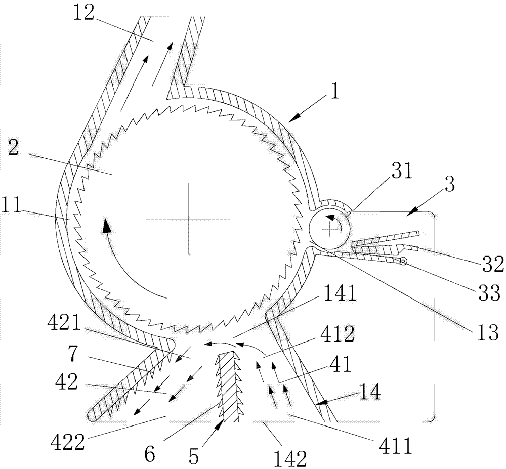
[0027] Embodiment one: if figure 1 , 2 As shown, the present embodiment includes a housing 1 with a carding chamber 11, and a carding roller 2 is installed in the carding chamber 11, and the housing 1 is provided with conveying fiber passages 12 communicated with the carding chamber 11 respectively. , feeding channel 13 and miscellaneous passage 14, feeding mechanism 3 is installed at feeding passage 13 places, miscellaneous passage 14 is positioned at housing 1 below, miscellaneous passage 14 comprises the miscellaneous inlet 141 near the carding chamber 11, and Away from the miscellaneous outlet 142 of the combing cavity 11 . The conveying fiber channel 12 is docked with the rotor, and the feeding mechanism 3 includes a feeding roller 31 , a feeding horn 32 , and a feeding plate 33 . The fiber strip is fed from the feeding horn 32, passes through the feeding plate 33 and the feeding roller 31, enters the carding chamber 11, and is decomposed into single fibers and single f...

Embodiment 2

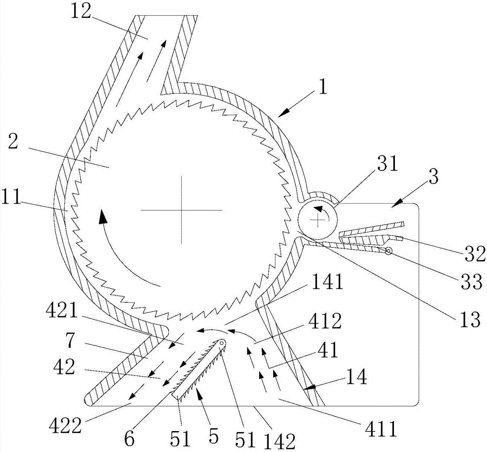
[0038] Embodiment two: if image 3 , 4 As shown, the difference from Embodiment 1 is that the end of the diverter plate 5 located at the miscellaneous inlet 141 is a hinged end 51, and the hinged end 51 is hinged in the miscellaneous discharge channel 14 through a rotating shaft; The end of 142 is swing end 52 . By pulling the splitter plate 5 , the splitter plate 5 is rotated around the rotating shaft, thereby changing the size of the air flow channel 41 and the impurity air flow channel 42 . Among them, the hinged end 51 is located in the middle of the miscellaneous inlet 141, and the miscellaneous inlet 141 is evenly divided into the outlet 412 of the air flow channel and the inlet 421 of the impurity air flow channel. Facts have proved that such a separation ratio can bring the best effect of removing impurities. , and can reduce the generation of backflow airflow, thereby preventing impurities from entering the carding chamber 11 due to backflow airflow. Wherein, takin...

Embodiment 3

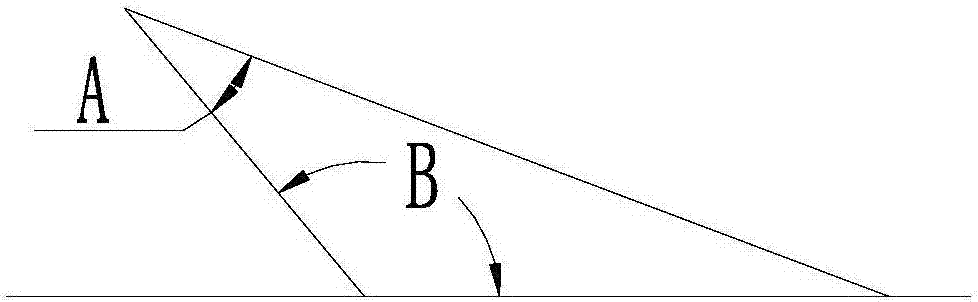
[0039] Embodiment three: as Figure 5 As shown, the difference from Embodiment 2 is that the splitter plate 5 is a fan-shaped structure, the end of the fan-shaped structure close to the center of the circle is the hinged end 51, and the end of the fan-shaped structure close to the arc is the swing end 52; the card clothing 6 is laid On the surface where the radius of the fan-shaped structure is located; the central angle of the splitter plate 5 is 60°. Wherein, the central angle can also be selected within the range of 30° to 60°. When the tip angle of the tines is 40° and the tooth back angle is 130°, if the central angle is 30°, the impurity content of the fibers discharged from the conveying fiber channel 12 is 0.005%; if the central angle is 45°, the fiber conveying channel The impurity content of the fibers discharged from 12 is 0.004%; if the central angle is 60°, the impurity content of the fibers discharged from the conveying fiber channel 12 is 0.003%.


PUM

PropertyMeasurementUnit
angleaaaaaaaaaa

Abstract

The invention discloses an impurity-removing carding device for a rotor spinning machine. The device comprises a shell and a carding roller, the shell is provided with a fiber transporting channel, a feeding channel and an impurity removing channel, the impurity removing channel comprises an impurity inlet and an impurity outlet, the impurity removing channel is internally provided with a spreader plate making the impurity removing channel divided into an air current channel and an impurity air current channel, on end of the spreader plate is located at the impurity inlet, the impurity inlet is divided into an air current channel outlet and an impurity air current channel inlet, the other end of the spreader plate is located at the impurity outlet, and the impurity outlet is divided into an air current channel inlet and an impurity air current channel outlet; card clothing is laid on the surface of the spreader plate, and the card clothing comprises sharp teeth arranged in the direction facing the impurity outlet. The size of the air flow channel is adjusted, so that the size of an air current is controlled, and the phenomenon that impurities low in density are brought back into a carding cavity by an air replenishment air current is prevented; in this way, the carding effect is improved, and the phenomenon that the quality of yarn spun through the next few steps is lowered is prevented.

Description

technical field [0001] The invention relates to a trash removal and carding device, in particular to a trash removal and carding device for a rotor spinning machine. Background technique [0002] The rotor spinning machine is mainly composed of rotor cup, false twist disk, yarn guide tube, yarn guide roller, fiber conveying channel, feeding roller, carding roller, trash removal and carding device and other components. The centrifugal force makes the fibers transferred from the carding cavity to the rotor coagulate to form whiskers (fiber rings), which are then twisted to form yarns. The rotor spinning machine is called rotor spinning because it uses the rotor to condense the single fiber. At the beginning, it mainly uses airflow, so it is also called air spinning. The characteristics of rotor spinning are high spinning speed, large winding capacity, good spinnability of low-grade cotton and waste noil, and greatly improved working environment. [0003] Among them, in order...

Claims


Application Information

Patent Timeline
Patent Type & Authority Applications(China)
IPC IPC(8): D01H4/32D01H4/36D01H4/34
CPCD01H4/32D01H4/34D01H4/36
Inventor 金玉珍朱世赫胡旭东
Owner ZHEJIANG SCI-TECH UNIV
Why Eureka
Try Eureka