A new drainage consolidation system and method

A new type of drainage consolidation technology, applied in infrastructure engineering, construction, soil protection, etc., can solve the problems of long consolidation period, easy blockage of drainage plates, and inconspicuous consolidation effect, so as to reduce post-construction settlement, Avoid blocking effects

Active Publication Date: 2018-11-27
SUN YAT SEN UNIV
View PDF5 Cites 0 Cited by
  • Summary
  • Abstract
  • Description
  • Claims
  • Application Information

AI Technical Summary

Problems solved by technology

[0004] The present invention provides a comprehensive vacuum water pump to solve the above-mentioned technical defects of the prior art in consolidating sludge landfill foundations and soft soil foundations, such as long consolidation period, easy blockage of drainage boards, and inconspicuous consolidation effect. High Pressure Consolidation System Pluggable by Pressure Dialysis and Its Corresponding Consolidation Method

Method used


Image

  • A new drainage consolidation system and method
  • A new drainage consolidation system and method
  • A new drainage consolidation system and method

Examples


Embodiment 1

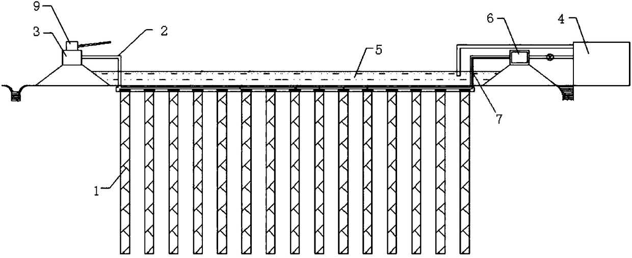
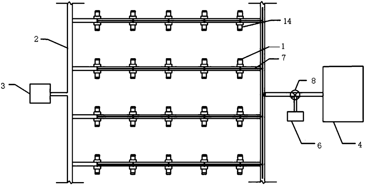
[0030] Such as figure 1 , 2 , 3, the consolidation system includes N drainage boards 1, vacuum pipes 2 and vacuum pumps 3, wherein the drainage board 1 is connected to the vacuum pump 3 through the vacuum pipes 2, and the drainage consolidation system also includes a salt solution storage chamber 4, a salt solution Pool 5, gas injection pressurization equipment 6, gas injection pipe 7, switch valve 8 and sprayer 9; wherein said drainage plate 1 is connected and communicated with one end of vacuum pipe 2 and one end of gas injection pipe 7, and the other end of gas injection pipe 7 is connected with injection pipe 7. The air pressurization device 6 is connected and communicated, and the saline storage chamber 4 is connected and communicated with the gas injection pipe 7 through the switch valve 8 . Where N is an integer greater than 1; the distance between the drainage boards 1 can be designed according to the physical and mechanical properties of the soft soil foundation, for...

Embodiment 2

[0035] The specific process of the consolidation system consolidated sludge landfill foundation and soft soil foundation provided by embodiment 1 is as follows:

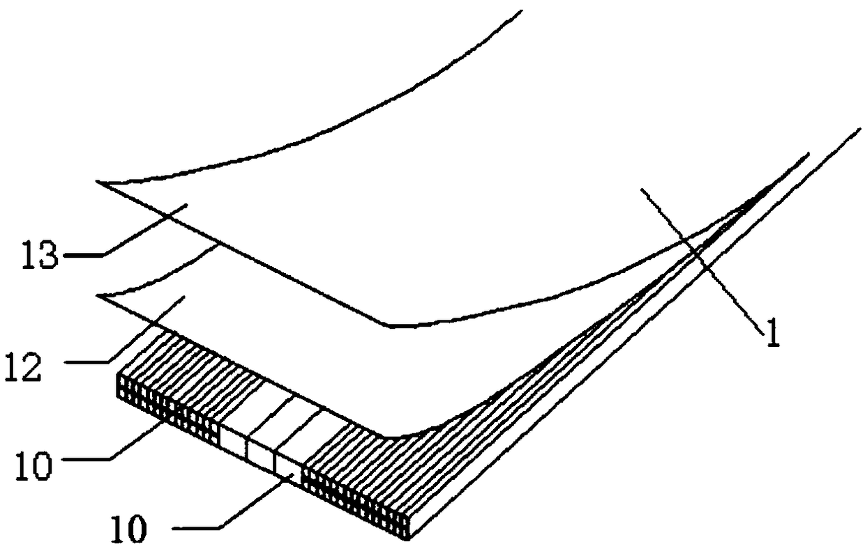
[0036] The first step is to install the drainage board after determining the vacuum preloading area. The distance between the drainage boards can be designed according to the physical and mechanical properties of the sludge landfill foundation and soft soil foundation. For example, the distance between the drainage boards is 1-2m. When laying the drainage board, the bottom of the drainage board is inserted into the board sleeve and bonded with strong glue to ensure that the salt solution and gas will not leak at the joint during the reinforcement process. The length of the board sleeve is 25-35 cm, and it is folded from the bottom 10 cm , Use the plugging machine to set the drainage board to the predetermined depth as a whole.

[0037] The second step is to cut off the geotextile filter membrane, dialysis membrane an...


PUM


Abstract

The invention relates to a novel draining consolidation system and method. According to the system and method, a pluggable high pressure consolidation system integrating vacuum hydraulic pressure dialysis is achieved, and a comprehensive method for efficient and coherent treatment for sludge filling foundations and a soft soil foundation draining consolidation carried out around a dialysis dehydrating method is achieved. The novel draining consolidation system comprises a plurality of novel water discharging plates, vacuum tubes and vacuum pumps, wherein the water discharging plates are connected with and communicate with the vacuum pumps through the vacuum tubes. The novel draining consolidation system further comprises a salt fluid storing chamber, an air injection supercharging device, an air injecting tube and a switching valve, wherein the water discharging plates are connected with and communicate with one ends of the vacuum tubes and one end of the air injecting tube, the other end of the air injecting tube is connected with and communicates with the air injection supercharging device, and the salt fluid storing chamber is connected with and communicates with the air injecting tube through the switching valve.

Description

technical field [0001] The invention relates to the technical field of foundation consolidation, and more specifically relates to a novel high-pressure consolidation system and consolidation method that can be plugged by comprehensive vacuum hydraulic dialysis. Background technique [0002] Economic development has brought about the improvement of people's living standards, resulting in an increasing amount of sewage. The sludge formed after sewage treatment in sewage plants is usually treated by landfill; construction operations in the sludge landfill area are faced with foundation problems. The problem of extremely low bearing capacity. On the other hand, with the development of the economy, in order to meet the land demand, some coastal cities will carry out land reclamation; the soft soil foundation formed by land reclamation has high moisture content and low strength, which cannot meet the needs of the project and needs to be reinforced. Complete the preloading and dra...

Claims


Application Information

Patent Timeline
Patent Type & Authority Patents(China)
IPC IPC(8): E02D3/10
CPCE02D3/10E02D3/103E02D2250/0053
Inventor 汤连生
Owner SUN YAT SEN UNIV
Why Eureka
Try Eureka