System for removing hydrogen sulfide from drilling fluid

A technology for removing system and drilling fluid, which is used in earth-moving drilling, flushing wellbore, wellbore/well components, etc., to facilitate installation and disassembly, ensure safety, and improve separation efficiency.

Inactive Publication Date: 2017-09-22
CHINA NAT PETROLEUM CORP CHUANQING DRILLING ENG CO LTD
View PDF7 Cites 16 Cited by
  • Summary
  • Abstract
  • Description
  • Claims
  • Application Information

AI Technical Summary

Problems solved by technology

[0005] In order to overcome the defects and deficiencies in the above-mentioned prior art, the purpose of the present invention is to solve the technical bottleneck that the existing underbalanced drilling Underbalanced Drilling in Sulfur Formation Possible

Method used


Image

  • System for removing hydrogen sulfide from drilling fluid
  • System for removing hydrogen sulfide from drilling fluid
  • System for removing hydrogen sulfide from drilling fluid

Examples


Embodiment 1

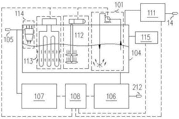
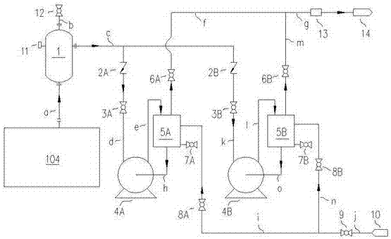
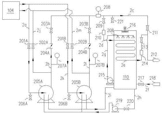
[0032] As a preferred embodiment of the present invention, with reference to the attached Figure 1-7 , this example discloses:

[0033]The drilling fluid hydrogen sulfide removal system is characterized in that it includes: a system inlet, a high-speed cyclone, a heating system, a stirring mechanism, an injection mechanism, a separation tank, a vacuum system, and a data monitoring and acquisition system. The system inlet and the high-speed cyclone The high-speed cyclone is connected to the heating system, the heating system is connected to the stirring mechanism, the stirring mechanism is connected to the spraying mechanism, and the high-speed cyclone, the heating system, the stirring mechanism and the spraying mechanism are arranged in The inside of the separation tank, the separation tank is connected with the vacuum system, the drilling fluid hydrogen sulfide removal system also includes: desulfurization agent injection system, centralized control system and liquid drainag...

Embodiment 2

[0035] As another preferred embodiment of the present invention, with reference to the attached Figure 1-7 , this example discloses:

[0036] The drilling fluid hydrogen sulfide removal system is characterized in that it includes: a system inlet, a high-speed cyclone, a heating system, a stirring mechanism, an injection mechanism, a separation tank, a vacuum system, and a data monitoring and acquisition system. The system inlet and the high-speed cyclone The high-speed cyclone is connected to the heating system, the heating system is connected to the stirring mechanism, the stirring mechanism is connected to the spraying mechanism, and the high-speed cyclone, the heating system, the stirring mechanism and the spraying mechanism are arranged in The inside of the separation tank, the separation tank is connected with the vacuum system, the drilling fluid hydrogen sulfide removal system also includes: desulfurization agent injection system, centralized control system and liquid ...

Embodiment 3

[0040] As another preferred embodiment of the present invention, with reference to the attached Figure 1-7 , this example discloses:

[0041] The drilling fluid hydrogen sulfide removal system is characterized in that it includes: a system inlet, a high-speed cyclone, a heating system, a stirring mechanism, an injection mechanism, a separation tank, a vacuum system, and a data monitoring and acquisition system. The system inlet and the high-speed cyclone The high-speed cyclone is connected to the heating system, the heating system is connected to the stirring mechanism, the stirring mechanism is connected to the spraying mechanism, and the high-speed cyclone, the heating system, the stirring mechanism and the spraying mechanism are arranged in The inside of the separation tank, the separation tank is connected with the vacuum system, the drilling fluid hydrogen sulfide removal system also includes: desulfurization agent injection system, centralized control system and liquid ...


PUM


Abstract

The invention relates to the technical field of petroleum drilling airtight drilling technologies, in particular to a system for removing hydrogen sulfide from drilling fluid, and the system is applicable to drilling operation for sulfur formations. The system for removing hydrogen sulfide from drilling fluid is characterized by comprising a system inlet, a high-speed hydrocyclone, a heating system, a mixing mechanism, a jetting mechanism, a separating tank, a vacuum system, a data monitor and collection system, a sulfur removal agent filling system, a centralized control system and a fluid drainage system. The hydrogen sulfide gas in the drilling fluid can be separated from hydrolyzed hydrogen sulfide in a completely airtight environment, the situation that hydrogen sulfide gas in the drilling fluid is volatilized in air at a conventional solid control system to cause harm to workers and damage to the environment can be avoided, and the requirement for safety of the drilling operation for the sulfur formations is met.

Description

technical field [0001] The invention relates to the technical field of oil drilling closed drilling technology, in particular to a drilling fluid hydrogen sulfide removal system used for drilling operations in sulfur-bearing formations. Background technique [0002] Underbalanced drilling is a drilling technology that makes the bottom hole pressure lower than the formation pressure. It has many advantages such as improving drilling efficiency, protecting reservoirs, and increasing oil and gas production. With the increasing intensity of exploration and development and the rapid development of deep well and ultra-deep well drilling technology, the proportion of hydrogen sulfide-containing reservoirs in the explored reservoirs is increasing. The current domestic technical regulations stipulate that when drilling operations in sulfur-bearing formations, when the concentration of hydrogen sulfide is greater than 50ppm, the underbalanced drilling technology cannot be used. There...

Claims


Application Information

Patent Timeline
Patent Type & Authority Applications(China)
IPC IPC(8): E21B21/06
CPCE21B21/067E21B21/068
Inventor 羡维伟韩烈祥陈科旭张鹏潘登任伟郑冲涛刘小玮刘先明程艳孙翊成何嵬
Owner CHINA NAT PETROLEUM CORP CHUANQING DRILLING ENG CO LTD
Why Eureka
Try Eureka