
Pseudorange positioning smoothing method and system, and positioning terminal

A pseudo-range and smoothing technology, applied in satellite radio beacon positioning system, radio wave measurement system, measuring device, etc., can solve the problem of low positioning accuracy, achieve the effect of improving positioning accuracy and reducing result errors

Inactive Publication Date: 2017-09-22
QIANXUN SPATIAL INTELLIGENCE INC
View PDF17 Cites 10 Cited by
  • Summary
  • Abstract
  • Description
  • Claims
  • Application Information

AI Technical Summary

Problems solved by technology

[0005] Embodiments of the present invention provide a pseudo-range positioning smoothing method and system, and a positioning terminal, aiming to solve the problem of low positioning accuracy in the prior art

Method used


Image

  • Pseudorange positioning smoothing method and system, and positioning terminal
  • Pseudorange positioning smoothing method and system, and positioning terminal
  • Pseudorange positioning smoothing method and system, and positioning terminal

Examples


Embodiment 1

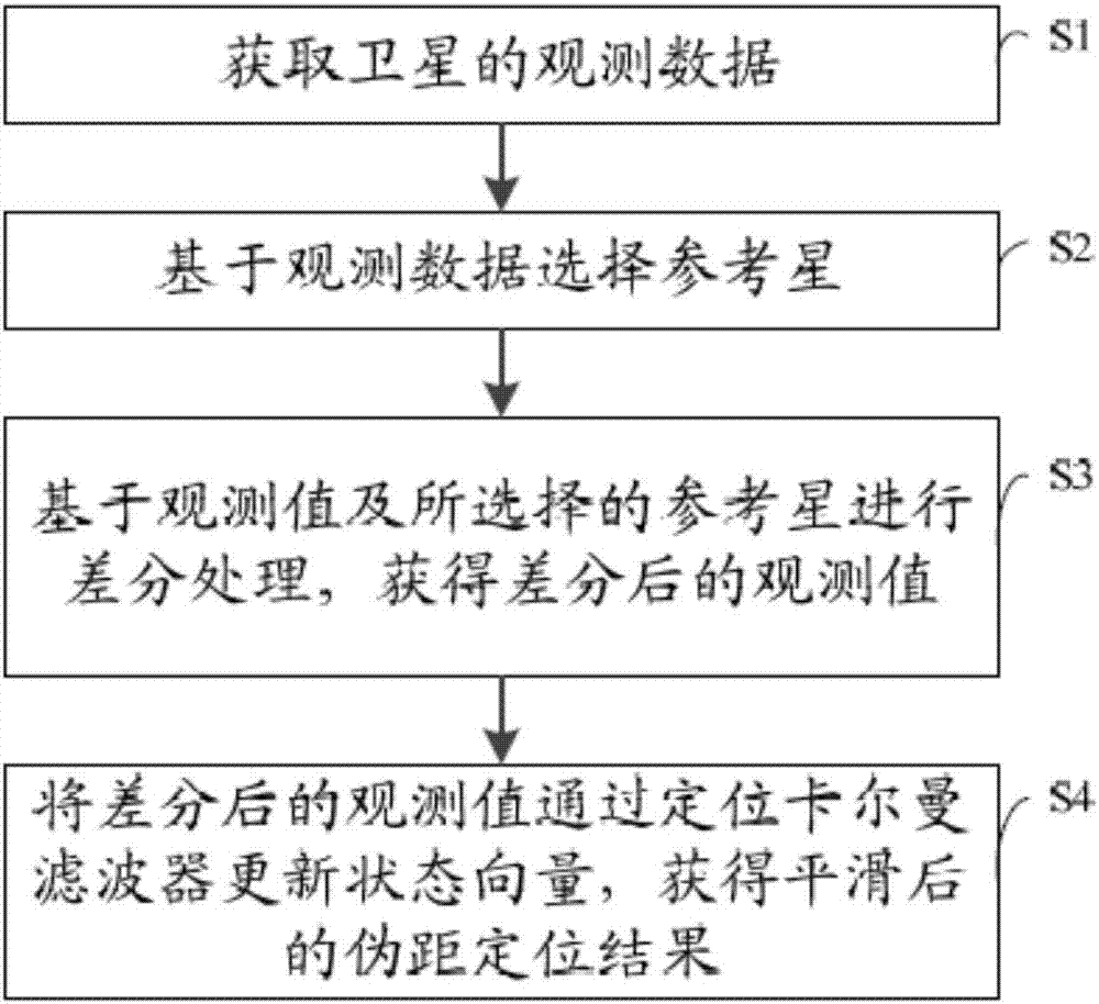
[0062] figure 1 It shows a flow chart of a pseudorange positioning smoothing method provided by the first embodiment of the present invention, including:

[0063] Step S1, acquiring satellite observation data, the observation data including observation values;

[0064] Specifically, the observation data of each tracked satellite is obtained, for example, the observation data of each satellite can be read from the tracking channel, and the observation data includes observation values ​​(such as Doppler pseudorange observation values, carrier phase observation values), etc., It may also include satellite tracking time, a clock, etc., which are not limited here.

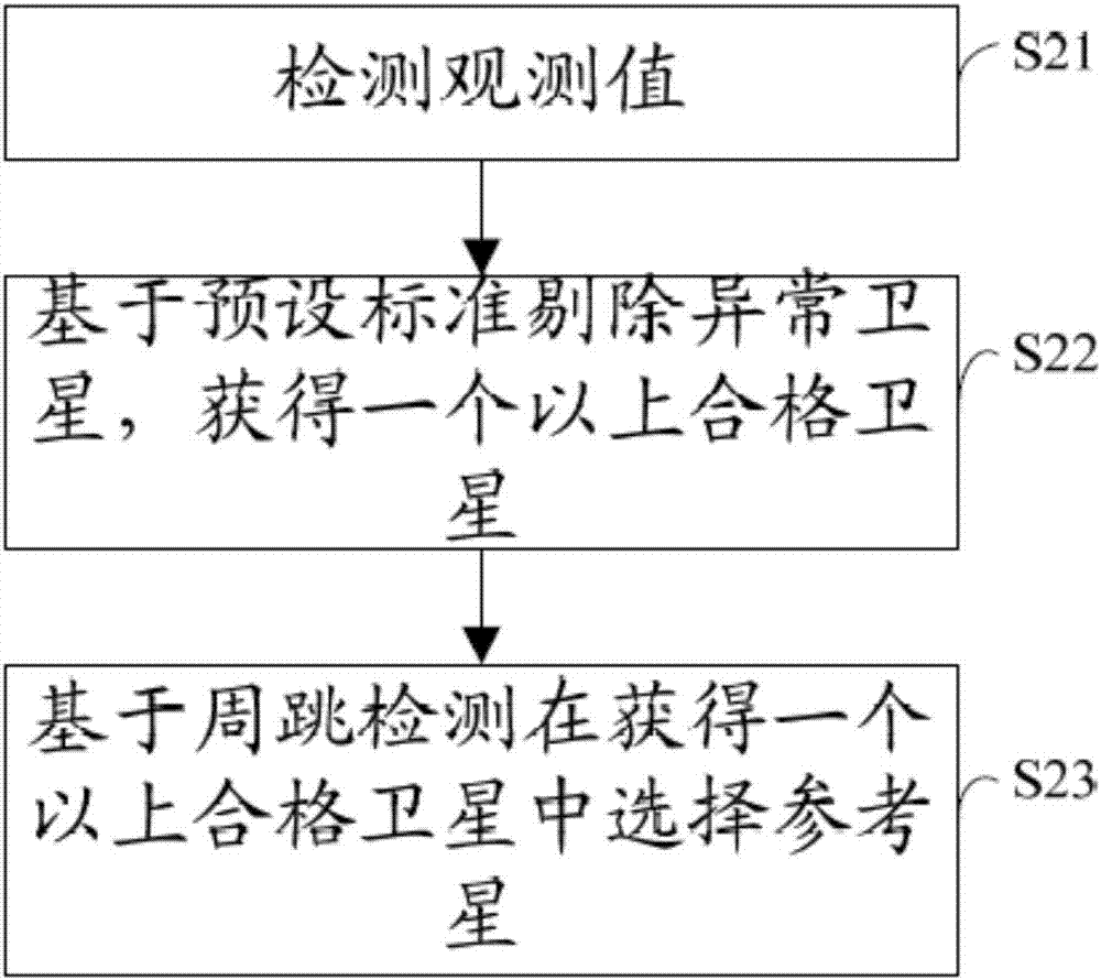
[0065] Step S2, selecting a reference star based on the observation data;

[0066] Specifically, a tracked satellite is selected as a reference star according to the acquired observation data.

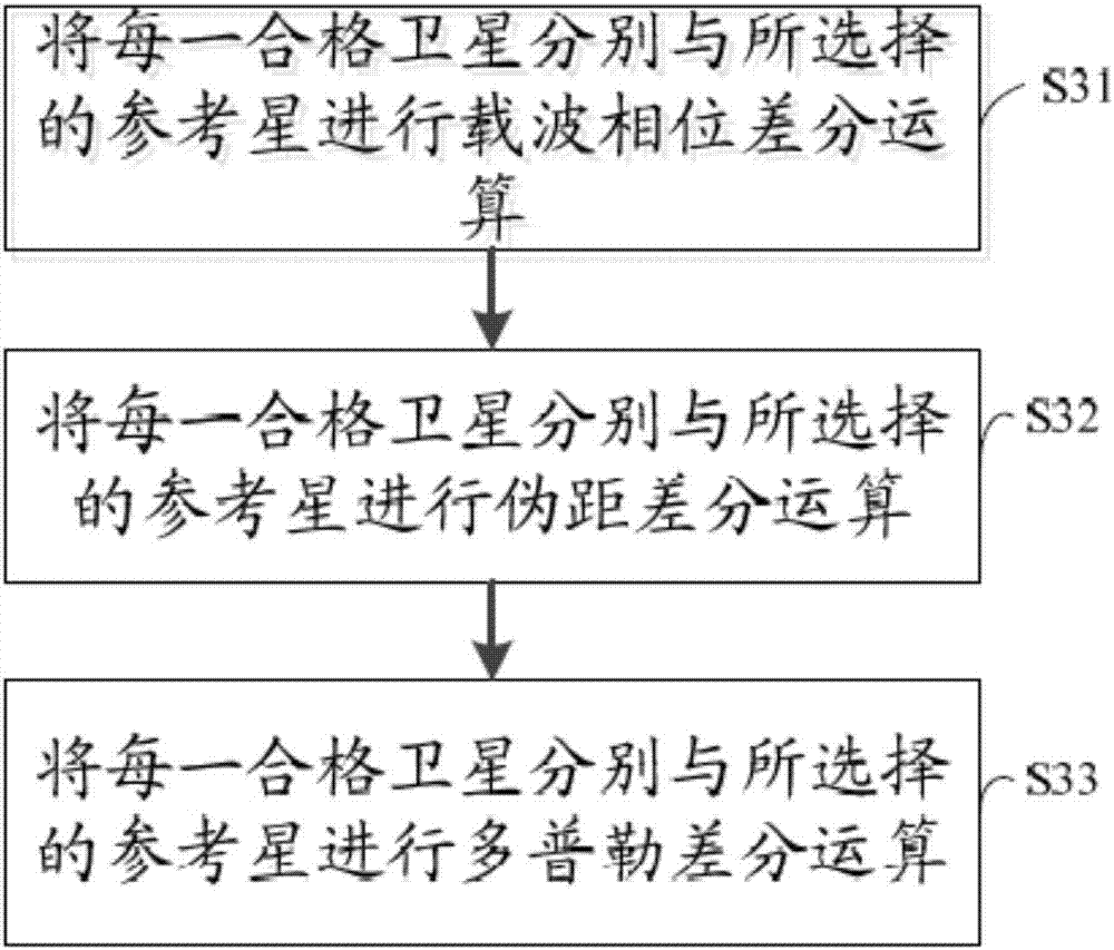
[0067] Step S3, perform difference processing based on the observed value and the selected reference star, and obtain the o...

Embodiment 2

[0139] Figure 8 It shows a structural diagram of a pseudorange positioning smoothing system provided by the second embodiment of the present invention, including: an acquisition module 1, a selection module 2 connected to the acquisition module 1, a differential processing module 3 connected to the selection module 2, and The smoothing module 4 connected to the difference processing module 3, wherein:

[0140] Obtaining module 1, used to obtain satellite observation data;

[0141] Specifically, the observation data of each tracked satellite is obtained, for example, the observation data of each satellite can be read from the tracking channel, and the observation data includes observation values ​​(such as Doppler pseudorange observation values, carrier phase observation values), etc., It may also include satellite tracking time, a clock, etc., which are not limited here.

[0142] Selection module 2, for selecting a reference star based on observation data;

[0143] Specifi...


PUM


Abstract

The invention discloses a pseudorange positioning smoothing method, a pseudorange positioning smoothing system and a positioning terminal. The pseudorange positioning smoothing method comprises the steps of: acquiring observation data of a satellite, wherein the observation data comprises an observed value; selecting a reference star based on the observation data; determining; conducting differential processing based on the observed value and the selected reference star to obtain an observed value after differencing, wherein the observed value after differencing comprises a pseudorange; and updating a state vector of the observed value after differencing through positioning a Kalman filter, so as to obtain a smoothed pseudorange positioning result. According to the pseudorange positioning smoothing method, the pseudorange positioning smoothing system and the positioning terminal, the observation data is acquired, the state vector is updated by using carrier phase increment, Doppler and eudorange after differencing at a positioning end directly without considering local clock skew, the pseudorange positioning error can be effectively reduced, and the positioning precision can be improved.

Description

technical field [0001] The invention belongs to the technical field of communication positioning, and in particular relates to a pseudo-range positioning smoothing method and system, and a positioning terminal. Background technique [0002] Satellite navigation and positioning technology has been widely used in aerospace, aviation, remote sensing, communication, surveying and mapping and other fields. With the growing demand for personal navigation and positioning services, GNSS (global navigation satellite system) has expanded from the initial positioning function to many fields, such as timing, vehicle navigation, telecommunications, earth science and even life safety. Due to its dual-use characteristics, GNSS is a strategic system related to national security and the success of future wars. All countries in the world are competing to develop GNSS systems. [0003] The basic positioning principle of GNSS is to calculate the user's position based on the position of four or...

Claims


Application Information

Patent Timeline
IPC IPC(8): G01S19/43
CPCG01S19/43
Inventor 蒋智
Owner QIANXUN SPATIAL INTELLIGENCE INC
Learn More