Method for realizing radio frequency signal switch handover circuit

A switching, radio frequency signal technology, used in electronic switches, electrical components, transmission systems, etc., can solve the problem of low sensitivity of antenna signals, and achieve the effect of improving self-detection capabilities

Inactive Publication Date: 2017-09-22
TIANJIN 764 COMM AIRMANSHIP
View PDF6 Cites 2 Cited by
  • Summary
  • Abstract
  • Description
  • Claims
  • Application Information

AI Technical Summary

Problems solved by technology

The sensitivity of the previous switch switching circuit to receive antenna signals is not high, and the power must be greater than or equal to -40dBm to identify and switch, but in fact the satellite signal received by the airborne antenna is less than -40dBm

Method used


Image

  • Method for realizing radio frequency signal switch handover circuit
  • Method for realizing radio frequency signal switch handover circuit
  • Method for realizing radio frequency signal switch handover circuit

Examples


Embodiment Construction

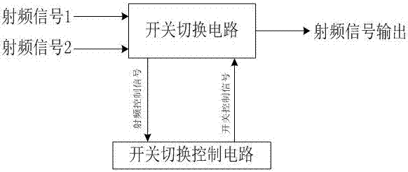
[0025] Such as Figure 1 to Figure 3 As shown, a method for implementing a radio frequency signal switching circuit includes a switching circuit, a switching control circuit, and the switching circuit is connected to the switching control circuit.

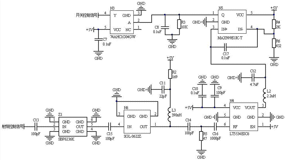
[0026] The switch switching circuit is connected as:

[0027] One end of capacitor C5 is connected to RF signal 2, the other end of capacitor C5 is connected to pin 4 of amplifier N2, pin 2 and pin 3 of amplifier N2 are grounded, pin 1 of amplifier N2 is respectively connected to one end of inductor L1 and capacitor C6, and the other end of inductor L1 One end is connected to capacitor C3 and one end of resistor R1 respectively, the other end of resistor R1 is connected to +5V power supply, the other end of capacitor C3 is grounded, the other end of capacitor C6 is connected to pin 2 of power divider U1, pin 1 of power divider U1, 3-pin, 4-pin, 5-pin, 6-pin, 8-pin, 10-pin, 11-pin, 12-pin are respectively grounded, 9-pin of power d...


PUM


Abstract

The invention relates to a method for realizing a radio frequency signal switch handover circuit. A radio frequency signal 1 enters a switch N1 chip, a radio frequency signal 2 is firstly amplified by an amplifier N2 to improve the sensitivity, and then is divided into two paths by a power divider U1, one path enters the switch N1 chip for handover, the other path of signal is firstly filtered by a filter Z1 to remove an interference signal and only maintain a Beidou signal, then the Beidou signal is amplified by an amplifier N6 to realize signal intensity that can be identified by a detector N4, is converted into a level by the detector N4 and is compared with a reference level through a comparator N5, when the level is higher than the reference level, a high level is output, and when the level is lower than the reference level, a low level is output; and then, the conversion of high level and the low level is realized by an inverter N3 to form a switch control signal level to control the switch N1 chip to hand over the signal. The circuit can automatically detect the power of a path of radio frequency signals to hand over the switch, and thus the problem of low sensitivity of the existing circuits is solved.

Description

technical field [0001] The invention relates to a method for realizing a radio frequency signal switching circuit, which is used in a radio frequency circuit of a satellite navigation anti-jamming antenna. Background technique [0002] The missile-borne satellite navigation anti-jamming antenna must not only be able to receive satellite signals for positioning by itself, but also receive the satellite signals received by the on-board antenna for positioning. Therefore, the missile-borne satellite navigation anti-jamming antenna generally has a combined circuit or A circuit in the form of a switch. The switch switching circuit has the advantages of high isolation and low insertion loss. The sensitivity of the previous switch switching circuit to receive antenna signals is not high, and the power must be greater than or equal to -40dBm to recognize and switch, but in fact the satellite signal received by the airborne antenna is less than -40dBm. Therefore, a switch switching...

Claims


Application Information

Patent Timeline
Patent Type & Authority Applications(China)
IPC IPC(8): H04B1/00H03K17/687
CPCH03K17/687H04B1/006H04B1/0067
Inventor 王长林
Owner TIANJIN 764 COMM AIRMANSHIP
Why Eureka
Try Eureka