Injection molding machine screw rod

A screw and screw technology for injection molding machines, applied in the field of injection molding machines, can solve problems such as energy waste, nozzle salivation, and inability to filter out

Active Publication Date: 2017-09-26
芜湖三顺机械制造有限公司
View PDF3 Cites 4 Cited by
  • Summary
  • Abstract
  • Description
  • Claims
  • Application Information

AI Technical Summary

Problems solved by technology

The injection molding machine mainly includes parts such as feeding mechanism, barrel, screw and nozzle; the existing feeding mechanism is mostly a single feeding funnel, which cannot better filter out the iron chips in the plastic raw materials; now Some barrels will lose a lot of heat during the production process, resulting in a waste of energy; the existing screw needs to move as a whole during the injection process, resulting in high energy consumption and greater wear; the existing nozzle There will be salivation when the injection is completed, resulting in contamination of the melt and waste of materials

Method used


Image

  • Injection molding machine screw rod
  • Injection molding machine screw rod
  • Injection molding machine screw rod

Examples


Embodiment 1

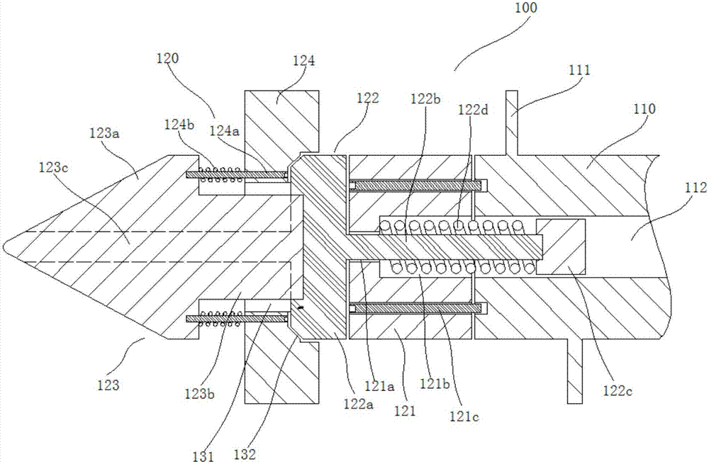
[0022] This embodiment provides an injection molding machine screw, which can be preferably used in various existing injection molding machines.

[0023] combine figure 1 As shown, a screw of an injection molding machine in this embodiment includes a screw body 100, the screw body 100 includes a screw body 110, a screw rib 111 is provided outside the screw body 110, and a hydraulic channel 112 is provided axially through the screw body 110; The left end of the screw main body 110 is provided with a screw head 120. The screw head 120 includes a mounting seat 121, a screw head seat 122, a screw head main body 123 and a non-return ring 124; The hydraulic channel 112 is provided with an installation channel 121a coaxially, and the installation channel 121a expands toward the outer circumference near the main body 123 of the screw head to form a spring cavity 121b; There is a screw head seat connecting rod 122b, and the screw head seat connecting rod 122b extends into the hydrauli...

Embodiment 2

[0034] This embodiment provides a nozzle structure for an injection molding machine, which can be preferably used in various existing injection molding machines.

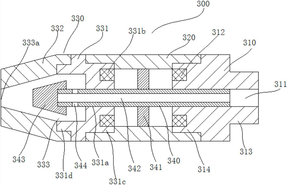
[0035] like image 3 As shown, a nozzle structure for an injection molding machine in this embodiment includes a nozzle body 300 .

[0036] The nozzle body 300 includes a nozzle seat 310, the left side of the nozzle seat 310 is connected with a hollow connecting sleeve 320, and the left side of the hollow connecting sleeve 320 is connected with a nozzle head 330; the nozzle head 330 includes a nozzle head mounting seat 331 and a nozzle cover 332, the nozzle head mounting seat 331 is connected with the hollow connecting sleeve 320, and the nozzle cover 332 is arranged at the nozzle head mounting seat 331;

[0037] The middle of the nozzle seat 310 and the nozzle head mounting seat 331 are coaxially provided with a material injection channel 311 and a sliding channel 331a, respectively. The left end surface of the n...

Embodiment 3

[0044] This embodiment provides a feeding device for an injection molding machine, which can be preferably used in various existing injection molding machines.

[0045] combine Figure 4 As shown, the feeding device of this embodiment includes a feeding device body 400 .

[0046] The main body 400 of the feeding device includes a feeding hopper 410. The upper opening of the feeding hopper 410 is a feeding port, and the bottom opening of the feeding hopper 410 is a feeding port; A protective cover 420 is provided on the outer side of the hopper 410, and a closed cavity is formed between the protective cover 420 and the feeding hopper 410; the inner side of the protective cover 420 is provided with a third excitation winding 430, and the inner side of the third excitation winding 430 is provided with a plastic layer 440. An independent dust collecting chamber 450 is formed between the layer 440 and the outer wall of the protective cover 420 , and an ash outlet 451 is provided a...


PUM


Abstract

The invention relates to the technical field of injection molding machines, in particular to an injection molding machine screw rod. The injection molding machine screw rod is characterized in that a hydraulic channel is formed in a screw rod main body; a screw rod head is arranged at the left end of the screw rod main body, and comprises a mounting seat, a screw rod head seat, a screw rod head body and a check ring; the mounting seat is arranged at the end face of the screw rod main body; a mounting channel is formed in the middle of the mounting seat; a spring cavity is formed in the mounting channel; the screw rod head seat comprises a screw rod head seat connecting seat and a screw rod head seat connecting rod; the screw rod head seat connecting rod stretches into the hydraulic channel; a piston is arranged at the right end of the screw rod head seat connecting rod; a first compression spring is arranged between the piston and the spring cavity; the screw rod head body comprises a screw rod head body head and a screw rod head body connecting part; the check ring is connected with the right end face of the screw rod head body head through connecting screw rods; the connecting screw rods are sleeved with second compression springs; a material channel is formed between an inner hole of the check ring and the screw rod head body connecting part; and a sealing surface is formed between the right end face of the check ring and the left end face of the screw rod head seat connecting seat. The injection molding machine screw rod is reasonable in structure and convenient in assembly.

Description

technical field [0001] The invention relates to the technical field of injection molding machines, in particular to a screw of an injection molding machine. Background technique [0002] Injection molding machine, also known as injection molding machine or injection machine, is the main molding equipment for making thermoplastic or thermosetting materials into various shapes of plastic products using plastic molding molds. With the acceleration of modernization construction, injection molding machines have been widely used in construction, packaging, electrical appliances, agriculture, automobiles, transportation, light industry, petrochemical industry, machinery industry, national defense industry and other sectors of the national economy and in various fields of people's lives , showing a very important role. The injection molding machine mainly includes a feeding mechanism, a barrel, a screw, a nozzle and other components; the existing feeding mechanism is mostly a singl...

Claims


Application Information

Patent Timeline
Patent Type & Authority Applications(China)
IPC IPC(8): B29C45/60B29C45/54
CPCB29C45/54B29C45/60
Inventor 周信国
Owner 芜湖三顺机械制造有限公司
Why Eureka
Try Eureka