Link-type multi-leg robot

A multi-legged robot and connecting rod technology, applied in the field of robotics, can solve the problems of restricting the movement space of the feet, achieve good dynamic response ability, reduce the overall weight, and facilitate the assembly and disassembly.

Inactive Publication Date: 2017-09-26
SHANGHAI UNIV
View PDF6 Cites 8 Cited by
  • Summary
  • Abstract
  • Description
  • Claims
  • Application Information

AI Technical Summary

Problems solved by technology

This structure has good rigidity and bearing capacity, but it needs to have more than two linear drive units, and the transmission distance of the connecting rod restricts the movement space of the foot end

Method used


Image

  • Link-type multi-leg robot
  • Link-type multi-leg robot
  • Link-type multi-leg robot

Examples


Embodiment 1

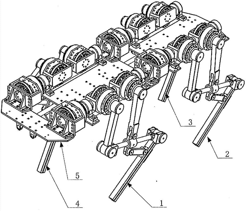
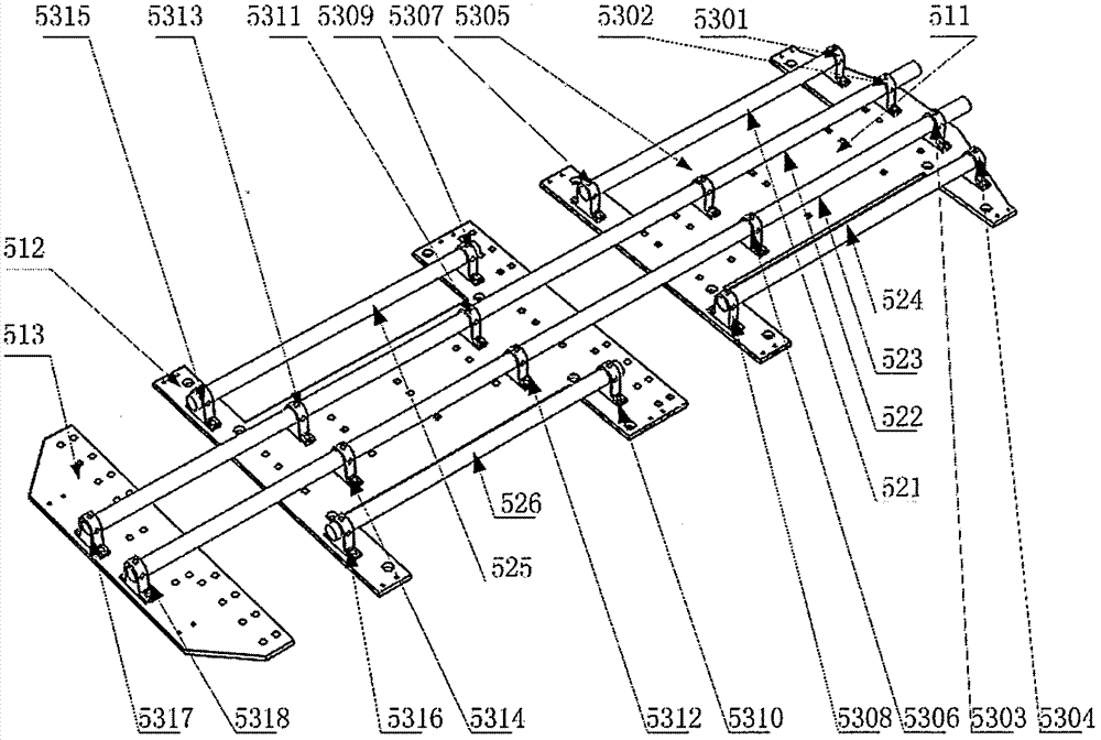
[0026] Such as figure 1 , figure 2 As shown, the robot comprises a left front foot unit 1, a left rear foot unit 2, a right front foot unit 3, a right rear foot unit 4, and a frame unit 5, wherein the frame unit 5 includes first to third base plates (511, 512 . 5309, 5310, 5311, 5312, 5313, 5314, 5315, 5316, 5317, 5318).

[0027] Such as figure 2 As shown, the bottom plate 511 is a carbon fiber plate molded part, and the connecting parts 5301, 5304, 5307, and 5308 are installed on the lower surface of the bottom plate 511 and symmetrically distributed outside its center line. The two ends of the connecting rod 521 The two ends of the connecting rod 524 are fixedly connected with the connecting piece 5307 and the connecting piece 5308 respectively. The connecting piece 5302, the connecting piece 5303, the connecting piece 5305 and the connecting piece 5306 are installed on the The lower surface is symmetrically distributed inwardly of its centerline.

[0028] The bottom ...

Embodiment 2

[0039] Such as Figure 8 As shown in the figure a in the middle, only the limit screw of the bearing end cover needs to be loosened, and the connecting rod of the thigh joint and the connecting rod of the lower leg are separated from the output shaft of the reducer of the thigh joint and the output shaft of the reducer of the lower leg respectively, so that the right forefoot unit can be realized. Rapid separation of drive structure and transmission structure.

[0040] Such as Figure 8 As shown in figure b in the middle, the transmission structure of the right forefoot unit 3 is turned over along the horizontal plane during assembly, so that the deformation from the elbow joint to the knee joint can be realized.

[0041] Such as Figure 8 As shown in figure c in the middle, connect the thigh joint connecting rod and the lower leg joint connecting rod with the output shaft of the lower leg joint reducer and the output shaft of the lower leg joint reducer respectively, and co...


PUM


Abstract

The invention discloses a link-type multi-leg robot which, based on bionic features of quadruped mammals, comprises four sets of foot modules and three-segment frame modules distributed symmetrically on two sides of a frame. The link-type multi-leg robot is characterized in that each foot unit employs a multi-link mechanism having a prismatic pair, and a hip joint, a thigh joint and a knee joint in each foot unit are driven in a transmission manner where an alternating-current permanent magnet synchronous motor and a harmonic reducer are connected; the modular foot design concept may allow foots and the frame to be quickly detached and attached to arrive at different configurations, and accordingly one robot may come with multiple models. The multi-link scaling foot structure used herein allows ratios of force and movement of thigh joints and shank joints to be amplified, and the requirement on motor output torque is lowered. The leg link structure has both high rigidity and bearing capacity. The legs can tolerate driving errors, the rigidity and stability of the whole structure are improved, and the robot is imparted better ability to adapt to complex terrains.

Description

technical field [0001] The invention belongs to the technical field of robots, and in particular relates to a link type multi-legged robot. Background technique [0002] Due to their unique body structure, multi-legged mammals have high dynamics, high stability, and high adaptability for locomotion. The multi-legged robot with bionic features developed by referring to bionics can not only realize dynamic walking, but also move at high speed. Traditional mobile robots such as existing wheeled and tracked robots need to keep in contact with the ground when moving, but footed robots can use isolated ground support instead of continuous support, and select the optimal support point in complex terrain to achieve Greater mobility and adaptability. If the auxiliary execution tool is combined with the motion platform composed of multi-legged robots, it can replace humans to complete tasks in dangerous environments, so it has broad application prospects. [0003] At present, the l...

Claims


Application Information

Patent Timeline
Patent Type & Authority Applications(China)
IPC IPC(8): B62D57/032
CPCB62D57/032
Inventor 陈添豪汪志威贾文川孙翊黄奕宁杨将
Owner SHANGHAI UNIV
Why Eureka
Try Eureka