A Novel Electrolyzer Sludge Discharging System and Its Method

An electrolytic cell and mud system technology, applied in the field of metallurgy, can solve problems such as high cost and low efficiency, and achieve the effects of preventing pipeline blockage, saving time, and increasing flushing speed.

Active Publication Date: 2020-05-19
HENAN ZHONGYUAN GOLD SMELTERY +1
View PDF10 Cites 0 Cited by
  • Summary
  • Abstract
  • Description
  • Claims
  • Application Information

AI Technical Summary

Problems solved by technology

[0015] The purpose of the present invention is to provide a novel electrolytic cell sludge discharge system in order to overcome the defects of low efficiency and high cost of the existing electrolytic cell sludge discharge system. The specific technical scheme is as follows:

Method used


Image

  • A Novel Electrolyzer Sludge Discharging System and Its Method
  • A Novel Electrolyzer Sludge Discharging System and Its Method
  • A Novel Electrolyzer Sludge Discharging System and Its Method

Examples


Embodiment 1

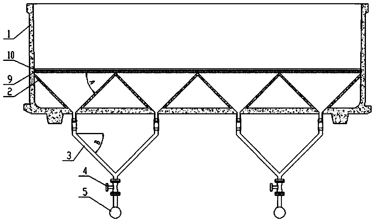
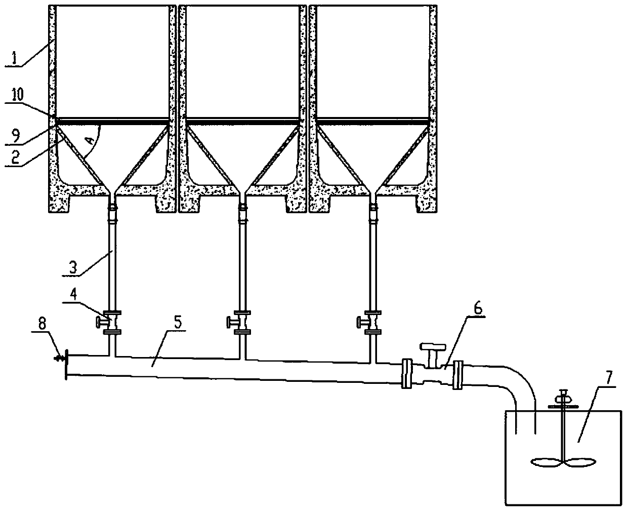
[0041] combine figure 2 as well as image 3As shown, a new copper electrolytic cell mud discharge system includes a copper electrolytic cell body 1, a settling cone 2 arranged at the bottom of the cell 1, and a lower sludge discharge branch pipe connected to the lower end of the settling cone 2 3. The lower mud discharge main pipe 5 of the electrolytic cell, the flushing fluid valve 8 and the anode slime collection tank 7 arranged at the lower end of the mud discharge branch pipe 3; Valve 4, one of the mud discharge branch pipe valve 4 controls two mud discharge branch pipes 3 at the same time, one end of the mud discharge main pipe 5 is installed with a flushing liquid valve 8, and the other end of the mud discharge main pipe 5 away from the flushing liquid valve 8 is installed in sequence There are mud discharge main pipe valve 6 and anode mud collection tank 7, each mud discharge main pipe 5 is connected with three mud discharge branch pipe valves 4 at the same time, and ...

Embodiment 2

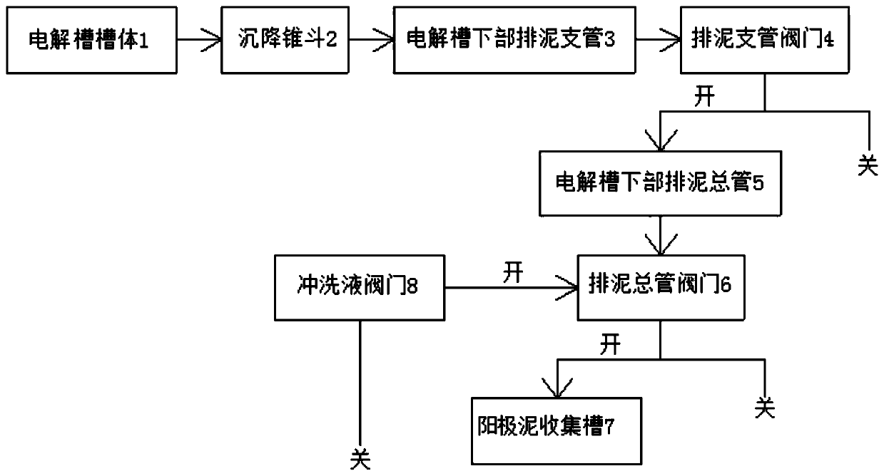
[0044] like figure 1 As shown, the intermittent sludge discharge method includes the following steps:

[0045] (1) Before the operation of the electrolysis system, close the valve 6 of the sludge discharge main pipe and the valve 8 of the flushing liquid, and open the valve 4 of the sludge discharge branch pipe;

[0046] (2) When the electrolysis system is running, the anode slime generated in real time in the upper part of the electrolytic cell 1 continuously falls to the settling cone 2 under the action of gravity, and then slides along the side of the settling cone 2 to the sludge discharge branch 3 under the tank and continue to slide along the branch pipe 3, and finally the anode mud enters the mud discharge main pipe 5 after passing through the mud discharge branch pipe valve 4;

[0047] (3) After the electrolysis system has been running for a period of time, close the sludge discharge branch pipe valve 4, open the sludge discharge main pipe valve 6 and the flushing liq...

Embodiment 3

[0050] like figure 1 Shown, continuous sludge discharge method, comprises the steps:

[0051] (1) Before the operation of the electrolysis system, open the mud discharge branch valve 4 and the mud discharge main pipe valve 6, and close the flushing liquid valve 8;

[0052] (2) When the electrolysis system is in operation, the anode slime generated in real time in the upper part of the electrolytic cell body 1 falls down to the settling cone bucket 2, the sludge discharge branch pipe 3, the sludge discharge branch pipe valve 4, the sludge discharge main pipe 5 and the discharge pipe in turn under the action of gravity. The mud main pipe valve 6 finally enters the anode slime collection tank 8 to complete the collection of anode slime; by adjusting the opening degree of the branch pipe valve 4 and the mud discharge main pipe valve 6, it is ensured that most of the anode slime and a small amount of solution enter the anode slime collection In the tank 7, but does not affect the ...


PUM

PropertyMeasurementUnit
diameteraaaaaaaaaa

Abstract

The invention discloses a novel electrolytic tank sludge discharge system and methods thereof and belongs to the technical field of metallurgy. The novel electrolytic tank sludge discharge system comprises an electrolytic tank body, a sedimentation conical hopper arranged at the bottom of the tank body, an electrolytic tank lower sludge discharge branched pipe connected with the lower end of the sedimentation conical hopper, an electrolytic tank lower sludge discharge header pipe arranged at the lower end of the sludge discharge branched pipe, a flushing liquid valve and an anode sludge collecting tank; and the end, close to the sludge discharge header pipe, of the electrolytic tank lower sludge discharge branched pipe is provided with a sludge discharge branched pipe valve, one end of the sludge discharge header pipe is provided with the anode sludge collecting tank, and the other end, away from the anode sludge collecting tank, of the sludge discharge header pipe is sequentially provided with a sludge discharge header pipe valve and a flushing liquid valve. The novel electrolytic tank sludge discharge methods are the intermittent sludge discharge method and the continuous sludge discharge method. According to the novel electrolytic tank sludge discharge system and the methods thereof, anode sludge generated in electrolyzing is discharged out of an electrolytic tank in real time, the backlogging time of the anode sludge in the electrolytic tank is greatly shortened, working efficiency is improved, a great amount of occupied funds are reduced, and cost is saved.

Description

technical field [0001] The invention belongs to the technical field of metallurgy, and in particular relates to a novel electrolyzer mud discharge system and a method thereof. Background technique [0002] At present, in the actual production of electrolytic refining in copper smelting enterprises, one anode cycle is 21 days, and the cleaning of anode slime generally adopts the method of centralized cleaning of one anode cycle, and the residence time of anode slime in the electrolytic cell is very long. Because the anode slime is rich in precious metals such as gold and silver, a serious backlog of precious metals such as gold and silver is caused in the electrolytic cell, which occupies a large amount of working capital and seriously affects the profitability of the enterprise. [0003] Anode slime is the residue accumulated from the anode and cathode deposits and the electrolyte flowing through the ditch when the electrolysis plant has been plating gold and silver on the p...

Claims


Application Information

Patent Timeline
Patent Type & Authority Patents(China)
IPC IPC(8): C25C7/06
CPCC25C7/06
Inventor 彭国敏陆业大廖忠义陈广华俎小凤崔宏志郭引刚徐庆新陈洋王家梁马立柱池文荣薛红伟
Owner HENAN ZHONGYUAN GOLD SMELTERY
Why Eureka
Try Eureka