Method for motion simulation of a manipulator

A motion simulation and manipulator technology, applied in the direction of manipulators, program-controlled manipulators, general control systems, etc., can solve the problems of manipulator components or manufacturing unit damage, long manufacturing unit accident time, high risk of collision, etc., to improve ergonomics Effect

Pending Publication Date: 2017-09-26
布勒特耶自动控制设备有限责任公司
View PDF6 Cites 2 Cited by
  • Summary
  • Abstract
  • Description
  • Claims
  • Application Information

AI Technical Summary

Problems solved by technology

It goes without saying that this is unacceptable from a job security point of view
It can occur that the risk of a collision due to incorrect assumptions about the geometry when attempting to manually pull out the robot is very high and this often leads to damage to the robot, the component or the manufacturing unit and thus also to a longer failure time of the manufacturing unit

Method used


Image

  • Method for motion simulation of a manipulator
  • Method for motion simulation of a manipulator
  • Method for motion simulation of a manipulator

Examples


Embodiment Construction

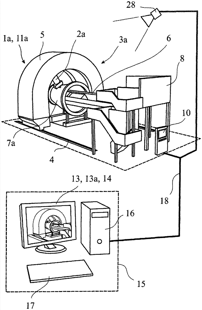
[0043] The exemplary embodiment described here relates to a robot 1a,b in a manufacturing cell in which riveting is produced on an aircraft structural component by means of a riveting device. Manipulators 1a, b are NC controlled. exist figure 1 The manufacturing cell of the first embodiment shown in is an Integrated Section Assembly Cell for machining 360°-aircraft fuselage components. The riveting device forms the end effector 2a of the manipulator 1a, which is here a 12-axis positioning machine. The production cells of the two exemplary embodiments, including all their associated components, respectively form a processing environment 3a, 3b in the sense of the above-mentioned definitions of the terms.

[0044] The end effector 2a is able to move on the inner surface of the processing arch 5 which moves along the floor rail 4, whereby the arch rail 4 and the processing arch 5 respectively form part not only of the processing environment 3a but also of the manipulator 1a. A...


PUM


Abstract

The invention relates to a method for motion simulation of a manipulator (1a,b), preferably a NC-controlled manipulator (1a,b), in a processing environment (3a,b), wherein the manipulator (1a,b) is moved in a working operation by a control device (10) and the processing environment (3a,b) is at least partially mapped in a model of the environment, said method comprising the steps of calculating a path planning (12a,b) by the control device (10) from a desired movement of the manipulator (1a,b) starting from an initial position (11a,b) and on the basis of a kinematic model of the manipulator (1a,b), carrying out a kinematic collision test on the basis of the path planning (12a,b), the kinematic model and the model of the environment, and generating a prediction result on the basis of the kinematic collision test. The method is characterized in that the initial position (11a,b) corresponds to the current state of the manipulator. The invention further relates to a corresponding computer program having a program code and to a corresponding system for motion simulation of a manipulator (1a,b).

Description

technical field [0001] The invention relates to a method for simulating the movement of a manipulator in a processing environment with the features stated in the preamble of claim 1 , a computer program with program code and a computer program with the features stated in the preamble of claim 17 A system for motion simulation of a manipulator in a processing environment, having the features stated in the preamble of claim 18. Background technique [0002] In robotics, the robot structure or the moving parts of an industrial robot are called manipulators. These robots are currently commonly used in automated manufacturing, for example for processing aircraft structural components. Examples include multi-axis crank-arm robots, which are used in corresponding manufacturing cells. The axis position of such a manipulator determines the reference position, including the axis direction, of the tool or end effector for the robot, which reference position is also referred to as the...

Claims


Application Information

Patent Timeline
IPC IPC(8): B25J9/16
CPCB25J9/1671B25J9/1676G05B2219/35308G05B2219/40311B25J9/16B25J9/1666B25J9/1694
Inventor D.艾克霍斯特M.迈尔
Owner 布勒特耶自动控制设备有限责任公司
Why Eureka
Try Eureka