

Method for recovering hexachlorodisilane from chlorosilane mixtures in process offgas streams
A technology of hexachlorodisilane and exhaust gas flow, which is applied in the direction of silicon compounds, silicon halide compounds, halosilanes, etc., can solve the problems of unfavorable high-reactivity solid substances and difficulties in eliminating high-boiling point components, and achieve low technical cost and Energy cost, low equipment complexity, effect of increased yield
- Summary
- Abstract
- Description
- Claims
- Application Information
AI Technical Summary
Problems solved by technology
Method used
Image

Examples
Embodiment 1
[0050] Embodiment 1 (comparative example)
[0051] 767.0 g of a chlorosilane mixture, corresponding to the high-boiling fraction of the distillation of the silicon production off-gas, were isolated by distillation. The fractions listed below were obtained. The base solution was not further tested.
[0052] Table 1. Composition profile of starting mixtures and fractions of comparative examples (TCS=trichlorosilane, STC=silicon tetrachloride, TCDS=tetrachlorodisilane, PCDS=pentachlorodisilane, HCDS=hexachlorodisilane)
[0053]
Embodiment 2
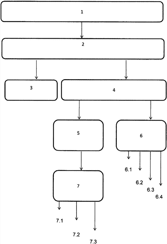
[0054] Embodiment 2 (according to figure 1 , response 5)
[0055] 0.4 g of the catalyst Amberlyst was mixed into 303.3 g of the chlorosilane mixture in a three-necked flask at 20 °C Composition was re-determined after one week (Table 2). The catalyst was filtered off and the mixture was separated by distillation. Three fractions were extracted. The third fraction or bottoms contains other higher boiling silicon compounds in addition to hexachlorodisilane.
[0056] Table 2. Composition profile of mixtures and fractions of Example 1 (TCS=trichlorosilane, STC=silicon tetrachloride, TCDS=tetrachlorodisilane, PCDS=pentachlorodisilane, HCDS=hexachlorodisilane, HSS = higher boiling silicon compounds). Composition was determined by NMR spectroscopy.
[0057]
Embodiment 3
[0058] Embodiment 3 (according to figure 1 , response 5)
[0059] In a three-necked flask at 20°C, 20.5 g of Amberlyst Mixed with 1352.3 grams (about 900 ml) of the chlorosilane mixture. The mixture was examined by NMR spectroscopy after one week. The catalyst was filtered off and the mixture was separated by distillation. 232.7 g of hexachlorodisilane were obtained (Table 3).
[0060] Table 3. Compositional profile of the mixture of Example 2 (TCS = trichlorosilane, STC = silicon tetrachloride, TCDS = tetrachlorodisilane, PCDS = pentachlorodisilane, HCDS = hexachlorodisilane, HSS = higher boiling point silicon compounds). Composition was determined by NMR spectroscopy.
[0061]
PUM
 Abstract
Description
Claims
Application Information