
Method for producing image display device, curable resin composition to be used therein, touch panel, and image display device

A technology for image display devices and curable resins, applied in the direction of non-polymer organic compound adhesives, identification devices, bonding methods, etc., can solve problems such as visibility problems, liquid crystal cell gap changes, and ripples

Active Publication Date: 2017-09-26
NIPPON KAYAKU CO LTD
View PDF7 Cites 1 Cited by
  • Summary
  • Abstract
  • Description
  • Claims
  • Application Information

AI Technical Summary

Problems solved by technology

[0005] However, in the case of producing an image display device by the above-mentioned method, after forming the cured product layer, if the weir portion of the cured ultraviolet curable resin is pressed with a finger or the like, force may be locally applied to the pressed portion, resulting in The gap of the liquid crystal cell changes, which causes ripples, causing problems in visibility when pressing

Method used


Image

  • Method for producing image display device, curable resin composition to be used therein, touch panel, and image display device
  • Method for producing image display device, curable resin composition to be used therein, touch panel, and image display device
  • Method for producing image display device, curable resin composition to be used therein, touch panel, and image display device

Examples


no. 1 approach

[0057] figure 1 It is a process drawing which shows 1st Embodiment of the manufacturing process of the image display apparatus (it is also called an "optical member") of this invention.

[0058] This method is a method of obtaining an optical member by bonding the liquid crystal display unit 1 and the protective plate 2 together.

[0059] The liquid crystal display unit 1 is a liquid crystal display unit in which a liquid crystal material is sealed between a pair of substrates on which electrodes are formed, and includes a polarizing plate, a driving circuit, a signal input cable, and a backlight unit.

[0060] figure 2 It is a cross-sectional view showing a main part of an example of the liquid crystal display unit 1 . Such as figure 2 As shown, this liquid crystal display unit 1 has a configuration in which a polarizing plate 22 is disposed on a liquid crystal display cell 21 , and a sealing body 23 is disposed on the liquid crystal display cell 21 so as to surround the...

no. 2 approach

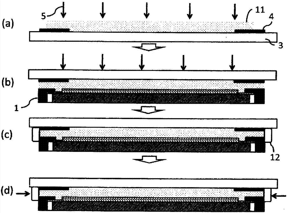
[0150] Figure 4 It is a process drawing which shows 2nd Embodiment of the manufacturing process of the optical member of this invention.

[0151] This method is a method of obtaining an optical member (image display device) by bonding the liquid crystal display unit 1 and the protective plate 2 together. It should be noted that, for the parts other than the changed parts compared with the first embodiment, the matters described in the above-mentioned first embodiment can be reflected and incorporated, and some descriptions that overlap are omitted.

[0152] [Process A]

[0153] First, if Figure 4 As shown in (a), the first curable resin composition 11 containing the (meth)acrylate (A) and the photopolymerization initiator (B) described later is coated on the protective plate 2 having the light-shielding portion 4 . On the surface of the face of the light shielding part 4 . As a coating method, a slit coater, a roll coater, a spin coater, a screen printing method, etc. ar...

no. 3 approach

[0178] Figure 5 It is a process drawing which shows 3rd Embodiment of the manufacturing process of the optical member of this invention.

[0179] This method is a method of obtaining an optical member (image display device) by bonding the liquid crystal display unit 1 and the protective plate 2 together. It should be noted that, for the parts other than the changed parts compared with the first embodiment, the matters described in the above-mentioned first embodiment can be reflected and incorporated, and some descriptions that overlap are omitted.

[0180] [Process A]

[0181] First, if Figure 5 As shown in (a), the first curable resin composition 11 containing the (meth)acrylate (A) and the photopolymerization initiator (B) described later is coated on the protective plate 2 having the light-shielding portion 4 . On the surface of the face of the light shielding part 4 . As a coating method, a slit coater, a roll coater, a spin coater, a screen printing method, etc. ar...


PUM

PropertyMeasurementUnit
Viscosityaaaaaaaaaa
Thicknessaaaaaaaaaa
Thicknessaaaaaaaaaa

Abstract

A method for producing an image display device having a protective plate adhered to a liquid crystal display unit equipped with a liquid crystal display cell, a polarizing plate, and a sealed body or a housing, the method involving: (A) a step for coating the liquid crystal display unit or the protective plate with a first curable resin composition; (B) a step for sticking the liquid crystal display unit and the protective plate to one another with the first curable resin composition interposed therebetween; and (C-I)-(C-III) the subsequently described steps which follow step (B). (C-I) a step for adhering the liquid crystal display unit and the protective plate to one another by curing the first curable resin composition; (C-II) a step for coating the outer-peripheral-side surface section of the protective plate, the sealed body or the housing with a second curable resin composition, so as to connect the liquid crystal display unit and the protective plate with one another; and (C-III) a step for, after step (C-II), providing the outer-peripheral side surface section of the protective plate, the sealed body or the liquid crystal display unit housing with a cured-article layer by curing the second curable resin composition.

Description

technical field [0001] This invention relates to the manufacturing method of the image display apparatus which manufactures an image display apparatus by bonding the optical base material which has a light-shielding part, and another optical base material, a curable resin composition used for this method, a touch panel, and an image display apparatus. Background technique [0002] In recent years, display devices in which a touch panel is bonded to a display screen of a display device such as a liquid crystal display, a plasma display, or an organic electroluminescent (EL) display to enable screen input have been widely used. This touch panel has a structure in which a glass plate or a resin film formed with a transparent electrode is bonded facing each other with a small gap, and a transparent protective plate made of glass or resin is bonded to the touch surface as necessary. [0003] There is a technology of using a double-sided adhesive sheet for bonding a glass plate or...

Claims


Application Information

Patent Timeline
IPC IPC(8): G02F1/1333C08F2/50C09J4/02C09J5/00C09J109/00C09J175/16G09F9/00
CPCC08F2/50C09J5/00C09J109/00C09J175/16G02F1/1333G09F9/00C08F20/18C09J2203/318C09J2301/312C09J2301/416G06F3/041
Inventor 水口贵文德田清久本桥隼
Owner NIPPON KAYAKU CO LTD
Learn More