Ceramic rolling and pressing machine

A technology of rolling machine and ceramics, which is applied in the direction of ceramic forming machines, forming indenters, manufacturing tools, etc., and can solve the problems of horizontal forward and backward movement, low production efficiency and high production cost

Inactive Publication Date: 2017-09-29
许文瑜 +1
View PDF5 Cites 1 Cited by
  • Summary
  • Abstract
  • Description
  • Claims
  • Application Information

AI Technical Summary

Problems solved by technology

However, because the existing rolling head stays in the ceramic container for a short time, especially in the middle of the ceramic container, it cannot move back and forth horizontally in the ceramic container. If the rolling head is small, it cannot Press to the middle position, and it is impossible to expand and roll the middle position of the ceramic container. Although a larger rolling head can press to the middle position of the ceramic container, the diameter of the upper opening (inlet) of the ceramic container needs to be relatively large. Or the internal diameter of the ceramic container is relatively small, so that the existing rolling head can only perform rolling operations on products with a small difference between the caliber of the upper mouth (entrance) of the ceramic container and the internal diameter of the ceramic container, such as bowls, pots, etc. , casserole and other ceramic containers, but it is impossible to perform rolling operations on products with a large difference between the diameter of the top (entrance) of the ceramic container and the inner diameter of the ceramic container, such as teapots and tea pots, such as teapots and tea pots. Containers can only be produced by injection molding, which has high production costs, low production efficiency, and time-consuming

Method used


Image

  • Ceramic rolling and pressing machine
  • Ceramic rolling and pressing machine
  • Ceramic rolling and pressing machine

Examples


Embodiment 1

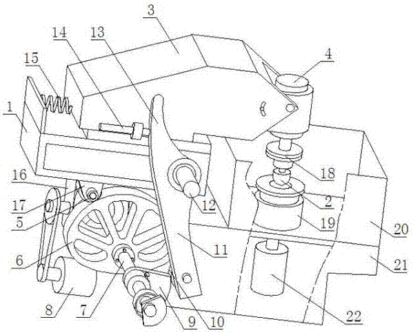
[0018] refer to figure 1 , the ceramic rolling machine comprises a body 21, a frame 1, a rolling head 2 and a rolling die 19, the rear of the body 21 is provided with a frame 1, and the rolling die 19 is arranged on the body 21, and the rolling die 19 is arranged on the body 21. The pressing die 19 is driven by the second rotating motor 22 below the body 21 , the rolling die 19 is fixed on the table of the body 21 by a clamp, and the rotating direction of the rolling die 19 is opposite to that of the rolling head 2 . The top of the frame 1 is slidably provided with a support beam 3, the rolling head 2 is driven by a first rotating motor 4, and the motor base of the first rotating motor 4 is rotationally connected with the end of the support beam 3, the The bottom of the frame 1 is provided with a first pulley 5 near the rear end, the first pulley 5 is in sliding contact with the edge of the lifting cam 6, the rotating shaft 7 of the lifting cam 6 is driven by a lifting motor 8...

Embodiment 2

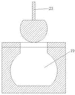
[0021] On the basis of Embodiment 1, in this embodiment, the shifting block 13 is arranged in an arc shape.

Embodiment 3

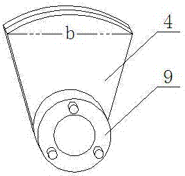
[0023] On the basis of Embodiment 1, in this embodiment, the rolling head 2 is set in a bowl shape with an arc-shaped bottom.


PUM


Abstract

The invention discloses a ceramic rolling and pressing machine, and belongs to the field of production of ceramic utensils. The ceramic rolling and pressing machine is characterized by comprising a rack and a rolling and pressing head, wherein a support beam is arranged on the rack in a sliding manner; the rolling and pressing head is driven by a rotating motor; a motor base of the rotating motor is in transmission connection with an end part of the support beam; a first pulley is arranged at the bottom, close to rear end, of the rack; the first pulley is in sliding contact with an edge of a lifting cam; a rotating shaft of the lifting cam is driven by a lifting motor; a crank is arranged on the rotating shaft of the lifting arm and is in sliding contact with the second pulley; the second pulley is rotatably arranged at bottom end of the connecting plate; a middle part of the connecting plate is rotatably arranged on a fixed shaft of the rack; the top part of the connecting plate extends upwards to form a pulling block; the support beam is provided with a connecting rod which can collide with the pulling block on the rear part of the pulling block; and the rear end of the support beam is connected with the rear end of the rack by a spring. According to the ceramic rolling and pressing machine disclosed by the invention, the rolling and pressing head can be positioned in a ceramic container for a long time, the inner surface of the ceramic container is fully rolled so as to prepare the ceramic container with small aperture and large inside diameter.

Description

Technical field: [0001] The invention relates to the field of ceramic rolling machines, in particular to a ceramic rolling machine. Background technique: [0002] The rolling head of the rolling machine is fixed on the front end of the frame of the rolling machine in the form of being perpendicular to the frame of the rolling machine, and the frame of the rolling machine swings up and down in the form of a lever, so that the rolling head Swing up and down to enter and exit the ceramic container to be rolled, and roll the middle part of the ceramic container through the rolling head in conjunction with the rotation of the ceramic container to form a ceramic container with an arc-shaped inner surface. The power source for the rolling head to swing up and down It comes from the large cam located at the rear of the rolling machine. The edge of the large cam is in sliding contact with the pulley at the rear of the frame. The large cam is eccentrically arranged on the output shaft...

Claims


Application Information

Patent Timeline
Patent Type & Authority Applications(China)
IPC IPC(8): B28B3/02
CPCB28B3/021
Inventor 许文瑜许新东
Owner 许文瑜
Why Eureka
Try Eureka