Injection system of injection molding machine
An injection system and injection molding machine technology, applied in the field of injection systems of injection molding machines, can solve problems such as energy waste, nozzle salivation, and inability to filter out
Active Publication Date: 2017-09-29
芜湖三顺机械制造有限公司
6 Cites 0 Cited by
AI-Extracted Technical Summary
Problems solved by technology
The injection molding machine mainly includes parts such as feeding mechanism, barrel, screw and nozzle; the existing feeding mechanism is mostly a single feeding funnel, which cannot better filter out the iron chips in the plastic raw materials; now Some barrels will lose a lot of heat during the production...
Method used
In conjunction with shown in Fig. 5, be provided with the first filter barrel 480 that opening is upward in the feed hopper 410, the edge of the upper end face of the first filter barrel 480 is connected with the inner circumference of the feeding port of the feed hopper 410, the first filter barrel 480 is connected with A blanking gap 481 is provided between the feeding hoppers 410; a second filter barrel 490 with an upward opening is rotatably provided in the first filter barrel 480, and the edge of the upper end surface of the second filter barrel 490 is connected with the inner circumference of the upper end surface of the first filter barrel 480. Connection; the side wall of the first filter barrel 480 is evenly distributed along the circumferential direction with a plurality of first strip-shaped openings 482 extending in the vertical direction, and the side wall of the second filter barrel 490 is evenly distributed along the circumferential direction. The second material strip-shaped mouth 491 extending in the vertical direction, the number of the first material strip-shaped mouth 482 is the same as the number of the second material strip-shaped mouth 491, by rotating the second filter barrel 490, the first filter The strip-shaped opening 482 can be fully closed or fully open. Through this structure, the plastic raw material can first enter the second filter barrel 490, and then flow into the blanking gap 481 through the second strip-shaped opening 491 and the first strip-shaped opening 482, which makes all the plastic raw materials They all flow to the discharge port against the inner wall of the feed hopper 410, so that the third excitation winding 430 can better clean up the iron chips in the plastic raw material. In addition, by adjusting the relative positions of the first strip-shaped opening 482 and the second strip-shaped opening 491, the particle size of the plastic raw material entering the blanking gap 481 can also be better screened, so that it can be better To ensure the uniformity of plastic raw materials. Moreover, when the injection molding is about to be completed, the first feeding bar-shaped opening 482 can be completely closed, so as to better prevent plastic raw materials from accumulating in the feeding hopper 410 .
In the present embodiment, sealing surface 132 comprises the sealing inclined-plane that is formed in screw head seat connection seat 122a end face edge place, and check ring 124 places is formed with the seal groove that is used for screw head seat connection seat 122a to stretch into, and seal groove structure There is a first sealing surface for sealingly fitting with the end surface of the screw head seat connecting seat 122a, a second sealing surface for fitting with the sealing inclined surface and a third sealing surface for fitting with the side surface of the screw head seat connecting seat 122a. Therefore, a better seal can be formed between the right end surface of the non-return ring 124 and the left end surface of the screw head seat connecting seat 122a.
In this embodiment, the left side of the nozzle sea...
Abstract
The invention relates to the technical field of injection molding machines, and relates to an injection system of an injection molding machine. The injection system comprises a threaded rod body and a nozzle body. The threaded rod body comprises a threaded rod main body. A threaded rod head is arranged at the left end of the threaded rod main body. The threaded rod head comprises an installation base, a threaded rod head base, a threaded rod head main body and a non-return ring. The nozzle body comprises a nozzle base. A hollow connection sleeve and a nozzle head are sequentially arranged on the left side of the nozzle base. The nozzle head comprises a nozzle head installation base and a nozzle cover. A material injection channel and a slide channel are coaxially arranged on the middle portion of the nozzle base and the middle portion of the nozzle head installation base correspondingly. The two ends of an ejector rod are matched with the material injection channel and the slide channel in a slidable and closed manner. A circular-ring-shaped first exciting winding is arranged on the portion, at the position of the inner side of the hollow connection sleeve, of the left end face of the nozzle base. A circular-ring-shaped second exciting winding is arranged on the portion, at the position of the inner side of the hollow connection sleeve, of the right end face of the nozzle head installation base. An annular iron plate is arranged at the position, located between the first exciting winding and the second exciting winding, on the outer side of the ejector rod. The injection system can well conduct injection on melt.
Technology Topic
EngineeringConductor Coil +3
Image
Examples
- Experimental program(5)
Example Embodiment
[0029] Example 1
[0030] This embodiment provides an injection molding machine screw, which can be better used in a variety of existing injection molding machines.
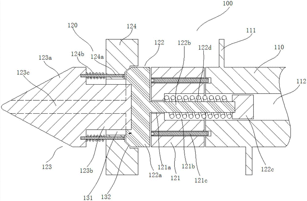
[0031] Combine figure 1 As shown, the screw of an injection molding machine in this embodiment includes a screw body 100, which includes a screw body 110. The screw body 110 is provided with a screw edge 111 on the outside, and the screw body 110 is provided with a hydraulic passage 112 along the axial direction. The screw body 110 is provided with a screw head 120 at the left end. The screw head 120 includes a mounting seat 121, a screw head seat 122, a screw head body 123 and a check ring 124; the mounting seat 121 is fixedly arranged at the end surface of the screw body 110, and the middle of the mounting seat 121 is connected to The hydraulic channel 112 is provided with a mounting channel 121a coaxially, and the mounting channel 121a is close to the main body 123 of the screw head and expands to the outer periphery to form a spring cavity 121b; the screw head base 122 includes a screw head base connecting base 122a, and the screw head base connecting base 122a is provided on the right side There is a screw head base connecting rod 122b, the screw head base connecting rod 122b extends into the hydraulic channel 112 through the mounting channel 121a; the right end of the screw head base connecting rod 122b is provided with a piston 122c, and the piston 122c and the left end surface of the spring cavity 121b are provided with a second A compression spring 122d; the screw head main body 123 includes a conical screw head main body head 123a, the right side of the screw head main body head 123a is provided with a cylindrical screw head main body connecting portion 123b, the screw head main body connecting portion 123b The right end is connected to the left side of the screw head base connecting seat 122a; the non-return ring 124 is connected to the right end surface of the screw head body head 123a through the connecting screw 124a, the connecting screw 124a is fixedly connected to the screw head body head 123a, and the connecting screw 124a is connected to the check The ring 124 can be slidably fitted. The connecting screw 124a is located between the check ring 124 and the screw head body head 123a, and a second compression spring 124b is sleeved; a material channel 131 is formed between the inner hole of the check ring 124 and the screw head main body connecting part 123b. A sealing surface 132 is formed between the right end surface of the check ring 124 and the left end surface of the screw head socket 122a.
[0032] In this embodiment, during plasticization, the screw head base connector 122a is pressed against the left end surface of the mounting base 121 under the action of the first compression spring 122d, and the molten plastic can push the non-return ring 124 to the left, thereby causing the melting The body can flow to the side of the screw head body 123 through the material channel 131. It should be understood here that the elastic force provided by the second compression spring 124b should be lower than the elastic force provided by the first compression spring 122d; during injection, the hydraulic channel 112 The hydraulic oil can be passed in to push the piston 122c to move to the left against the first compression spring 122d. At this time, the non-return ring 124 is pressed against the screw head connecting seat 122a under the action of the second compression spring 124b, so as to better Prevent the melt at the side of the screw head body 123 from flowing backward.
[0033] Through the above structure, the screw main body 110 does not need to move in the axial direction during injection in this embodiment, which can better reduce the wear of the thread 111, and also does not require excessive external force during the injection process. It is better to reduce the injection cost.
[0034] In addition, in this embodiment, the screw head base connecting rod 122b and the piston 122c are threadedly connected, and the screw head main body connecting portion 123b and the screw head base connecting seat 122a are also threadedly connected. This makes it possible for this embodiment to first insert the screw head base connecting rod 122b into the mounting channel 121a, and then to install the first compression spring 122d and the piston 122c in sequence, and then install the mounting base 121 into the end surface of the screw body 110 Secondly, turn the non-return ring 124 into the screw head body 123, and then connect the screw head main body connecting portion 123b and the screw head base connecting seat 122a to complete the assembly; thereby facilitating assembly.
[0035] In this embodiment, the mounting base 121 is connected to the screw head main body 123 through a hexagon socket screw 121c, so that the connection between the mounting base 121 and the screw main body 110 is preferably realized.
[0036] In this embodiment, the screw head base connecting rod 122b is hermetically fitted with the mounting channel 121a. Therefore, it is possible to better prevent the melt from flowing into the screw body 110.
[0037] In this embodiment, the sealing surface 132 includes a sealing bevel formed at the edge of the end face of the screw head base connection base 122a, and the non-return ring 124 is formed with a sealing groove for the screw head base connection base 122a to extend into, and the sealing groove is configured to communicate with The first sealing surface of the end face of the screw head base connection base 122a is hermetically fitted, the second sealing surface used for mating with the sealing slope, and the third sealing surface used for mating with the side surface of the screw head base connection base 122a. Therefore, a better seal can be formed between the right end surface of the non-return ring 124 and the left end surface of the screw head base connecting seat 122a.
[0038] As an improvement of this embodiment, a sliding groove can be further provided on the left end surface of the mounting seat 121, and the screw head base connecting seat 122a can slidably fit with the sliding groove. This can further prevent the melt from flowing into the screw body 110.
[0039] In this embodiment, a material flow channel 123c is provided on the outer side of the screw head body 123 along the axial direction. This facilitates the flow of the melt.
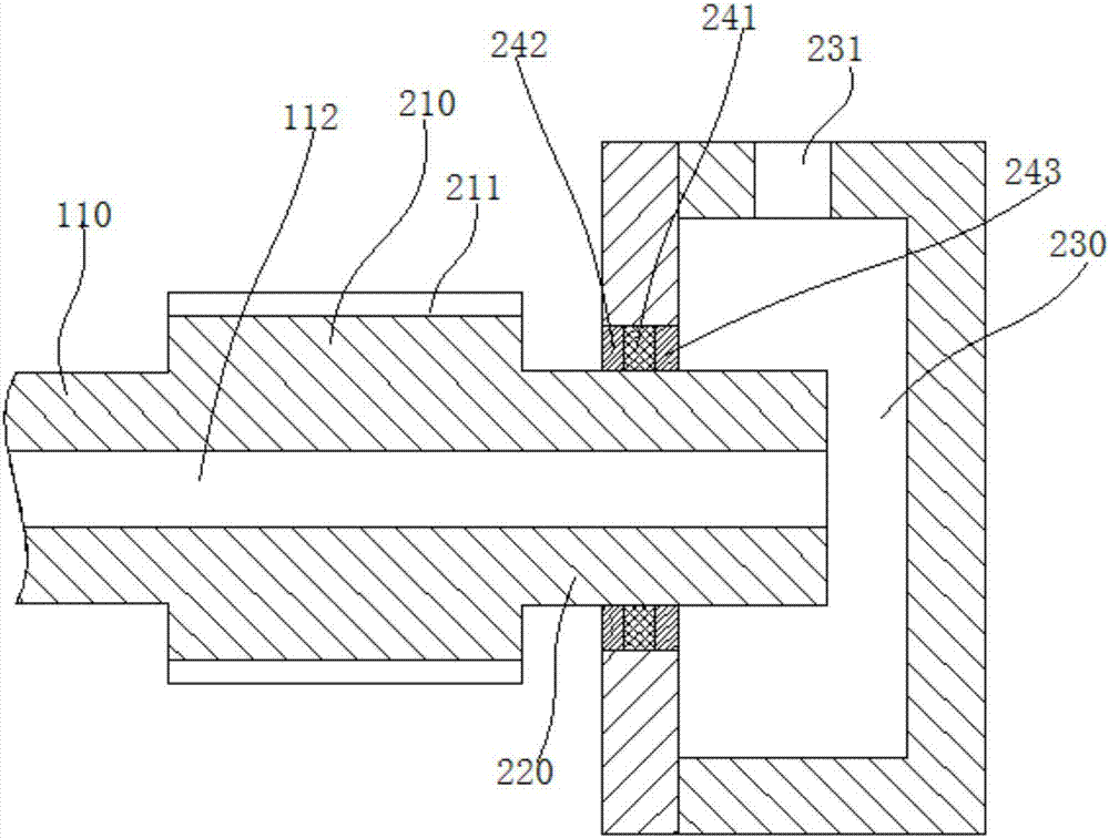
[0040] Combine figure 2 As shown, the rear end of the screw body 110 is provided with a transmission part 210, and the side wall of the transmission part 210 is provided with a key groove 211. The key groove 211 can be fixedly matched with the transmission gear circumferentially, so as to better facilitate the transmission of external power to the screw through the gear transmission. The main body 110; in addition, the right side of the transmission part 210 is provided with a rotating part 220, the rotating part 220 is matched with a side wall of a hydraulic oil tank 230 through a bearing 241, and the rotating part 220 extends into the hydraulic oil tank 230, and both sides of the bearing 241 are respectively provided The first oil seal 242 and the second oil seal 243 are provided with a hydraulic oil inlet 231 at the hydraulic oil tank 230. With this structure, the hydraulic oil can flow into the hydraulic channel 112 through the hydraulic oil tank 230 to push the piston 122c, so that the entry of the hydraulic oil will not be disturbed by the rotation of the screw body 110.
Example Embodiment
[0041] Example 2
[0042] This embodiment provides a nozzle structure for an injection molding machine, which can be better used in a variety of existing injection molding machines.
[0043] Such as image 3 As shown, a nozzle structure for an injection molding machine in this embodiment includes a nozzle body 300.
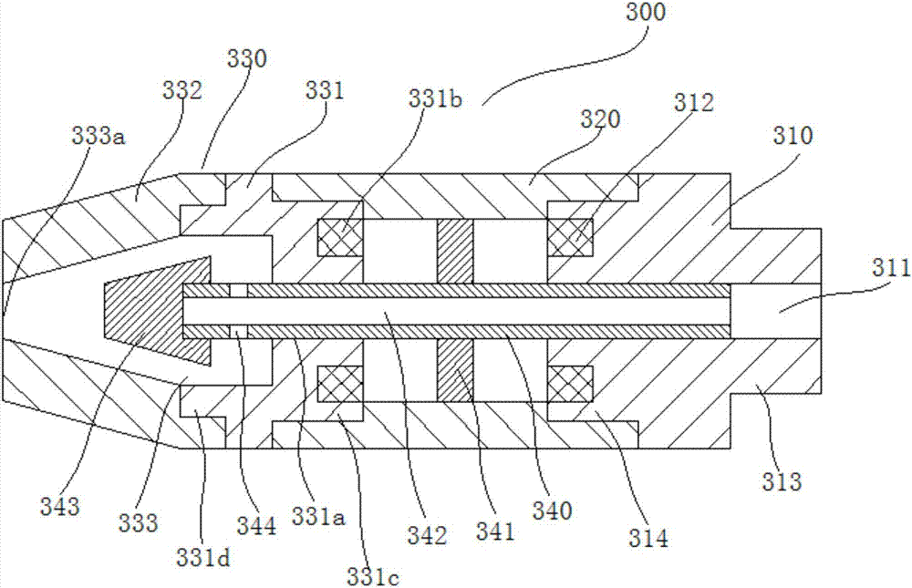
[0044] Wherein, the nozzle body 300 includes a nozzle base 310, the left side of the nozzle base 310 is connected with a hollow connecting sleeve 320, and the left side of the hollow connecting sleeve 320 is connected with a nozzle head 330; the nozzle head 330 includes a nozzle head mounting seat 331 and a nozzle cover 332. The nozzle head mounting seat 331 is connected with the hollow connecting sleeve 320, and the nozzle cover 332 is provided at the nozzle head mounting seat 331;
[0045] The injection nozzle base 310 and the nozzle head mounting base 331 are coaxially provided with an injection channel 311 and a sliding channel 331a respectively in the middle, and both ends of a top rod 340 are slidably fitted with the injection channel 311 and the sliding channel 331a respectively; An annular first excitation winding 312 is provided on the left end of the nozzle base 310 at the inner side of the hollow connecting sleeve 320, and an annular second excitation winding 331b is provided on the right end of the nozzle head mounting base 331 at the inner side of the hollow connecting sleeve 320. A ring-shaped iron plate 341 is provided on the outer side of the top rod 340 between the first field winding 312 and the second field winding 331b;
[0046] An injection cavity 333 is formed between the nozzle head mounting seat 331 and the injection nozzle cover 332. The middle of the ejector rod 340 is provided with an injection channel 342 for communicating the injection channel 311 and the injection cavity 333 along the axial direction; the injection cavity 333 is located The shape of the nozzle cover 332 is constructed into a truncated cone shape that gradually shrinks from right to left, and the injection cavity 333 forms an injection port 333a at the left end surface of the nozzle cover 332; a top block 343 is provided at the left end of the top rod 340, and the top block 343 The outer wall can be hermetically fitted with the inner wall of the injection cavity 333 at the nozzle cover 332; the ejector 340 is located on the side wall of the injection cavity 333 with an injection port 344 communicating with the injection channel 342, and the injection port 344 is connected to the iron The distance between the plates 341 is greater than the distance between the left end surface of the sliding channel 331 a and the iron plate 341.
[0047] In the nozzle structure of this embodiment, during injection, the first excitation winding 312 can pass the excitation current, so that the first excitation winding 312 can absorb the iron plate 341. At this time, the melt can pass through the injection channel 311. The runner 342 flows from the injection port 344 into the cavity 333, so that the melt can flow into the mold from the injection port 333a; when the injection is completed, the second excitation winding 331b can pass the excitation current, so that the second The field winding 331b can absorb the iron plate 341, and the top block 343 can immediately seal the injection port 333a from the inside, which can better prevent material waste and production hazards caused by the outflow of the melt in the injection cavity 333 problem.
[0048] In this embodiment, the right side of the nozzle base 310 is provided with a first mounting platform 313 protruding outward, and the outer wall of the first mounting platform 313 is provided with external threads. Thus, the nozzle base 310 can be better installed at the barrel of the injection molding machine.
[0049] In this embodiment, a second mounting platform 314 protruding outward is provided on the left side of the nozzle base 310, a third mounting platform 331c protruding outward is provided on the right side of the nozzle head mounting seat 331, and both ends of the hollow connecting sleeve 320 are provided There are first threaded mounting grooves for threadedly fitting with the second mounting table 314 and the third mounting table 331c, respectively. Therefore, the structure is simple and easy to assemble.
[0050] In this embodiment, the left side of the nozzle head mounting seat 331 is provided with a fourth mounting platform 331d protruding outward, and the nozzle cover 332 is provided with a second threaded mounting groove for threaded engagement with the fourth mounting platform 331d. Therefore, the structure is simple and easy to assemble.
Example Embodiment
[0051] Example 3
[0052] In this embodiment, a feeding device for an injection molding machine is provided, which can be preferably used in a variety of existing injection molding machines.
[0053] Combine Figure 4 As shown, the feeding device of this embodiment includes a feeding device body 400.
[0054] Wherein, the feeding device body 400 includes a feeding hopper 410, the upper opening of the feeding hopper 410 is a feeding port, and the lower opening of the feeding hopper 410 is a discharge port; a plurality of screen holes 411 are provided on the side wall of the feeding hopper 410, and the feeding The outer side of the hopper 410 is provided with a protective cover 420, and a closed cavity is formed between the protective cover 420 and the feeding hopper 410; the inner side of the protective cover 420 is provided with a third field winding 430, and the inner side of the third field winding 430 is provided with a plastic layer 440. An independent dust collection chamber 450 is formed between the layer 440 and the outer wall of the protective cover 420, and the bottom of the dust collection chamber 450 is provided with an ash outlet 451.
[0055] In this embodiment, the plastic raw material can enter the hopper 410 from the feeding port. When the excitation current is applied to the third field winding 430, the iron chip doped in the plastic raw material can be adsorbed to the dust collection chamber 450 through the mesh 411 It should be understood that the aperture of the mesh 411 should satisfy the condition that the plastic material will not pass through the mesh 411. In addition, when the third field winding 430 is no longer supplied with excitation current, the iron cut in the dust collection chamber 450 can fall into the bottom of the dust collection chamber 450 and then fall out from the dust outlet 451, thereby better achieving dust collection Periodic cleaning function of cavity 450.
[0056] Combine Figure 5 As shown, the feed hopper 410 is provided with a first filter bucket 480 with an upward opening. The upper end edge of the first filter bucket 480 is connected to the inner periphery of the feeding port of the feed hopper 410. The first filter bucket 480 and the feed hopper 410 are provided between There is a blanking gap 481; the first filter bucket 480 is rotatably provided with a second filter bucket 490 with an upward opening, and the upper edge of the second filter bucket 490 is connected with the inner periphery of the upper end surface of the first filter bucket 480; The side wall of the 480 is evenly distributed along the circumferential direction with a plurality of first strip-shaped openings 482 extending in the vertical direction, and the side wall of the second filter bucket 490 is evenly distributed along the circumferential direction with a plurality of extending in the vertical direction The second feed strip opening 491, the number of the first feed strip opening 482 is the same as the number of the second feed strip opening 491, by rotating the second filter barrel 490, the first feed strip opening 482 can Is completely closed or completely opened. Through this structure, the plastic raw materials can first enter the second filter barrel 490, and then flow into the blanking gap 481 through the second strip-shaped opening 491 and the first strip-shaped opening 482, which makes all plastic raw materials All of them flow against the inner wall of the hopper 410 to the discharge port, so that the third field winding 430 can better clean the iron shavings in the plastic raw material. In addition, by adjusting the relative positions of the first strip-shaped opening 482 and the second strip-shaped opening 491, the particle size of the plastic raw materials entering the blanking gap 481 can also be better screened, so as to better To ensure the uniformity of plastic raw materials. In addition, when the injection molding is about to be completed, the first feed strip opening 482 can be completely closed, so that the accumulation of plastic raw materials in the hopper 410 can be better prevented.
[0057] In this embodiment, the upper part of the hopper 410 is configured as a hollow cylinder, and the lower part of the hopper 410 is configured as a hollow truncated cone with an inner diameter gradually decreasing from top to bottom. So as to facilitate cutting.
[0058] In this embodiment, a discharge pipe 460 is connected to the discharge port of the hopper 410, and a feeding screw 461 is provided inside the discharge pipe 460. So as to facilitate cutting.
[0059] In this embodiment, a sealing cover 470 is detachably provided at the feeding port of the hopper 410, and the upper part of the sealing cover 470 is provided with a feeding pipe 471. Therefore, the inside of the hopper 410 can be better protected.
PUM


Description & Claims & Application Information
We can also present the details of the Description, Claims and Application information to help users get a comprehensive understanding of the technical details of the patent, such as background art, summary of invention, brief description of drawings, description of embodiments, and other original content. On the other hand, users can also determine the specific scope of protection of the technology through the list of claims; as well as understand the changes in the life cycle of the technology with the presentation of the patent timeline. Login to view more.