Low-resistance internal mixing type gas nucleus atomization oil gun

An internal mixing, low-resistance technology, applied in the direction of lighting and heating equipment, burners, etc., can solve the problems of flame trailing, affecting fuel utilization, endangering boiler safety, etc., and achieve the effect of ensuring the atomization effect

Pending Publication Date: 2017-09-29
SHANGHAI WISEBOND TECH
View PDF5 Cites 1 Cited by
  • Summary
  • Abstract
  • Description
  • Claims
  • Application Information

AI Technical Summary

Problems solved by technology

The oil guns currently in the market are difficult to meet the high load demand, especially the oil guns with an output of more than 3.5t / h have problems such as large atomized particle size and difficulty for combustion-supporting air to penetrate the oil mist layer, resulting in incombustible combustion. Stability, black smoke, flame tailing and other problems affect the utilization rate of fuel and endanger the safety of boilers in severe cases
In addition, the existing oil gun has the problem of large resistance and serious pressure loss, so high oil pressure is required, which limits the range of use of the oil gun and brings difficulties to the system

Method used


Image

  • Low-resistance internal mixing type gas nucleus atomization oil gun
  • Low-resistance internal mixing type gas nucleus atomization oil gun
  • Low-resistance internal mixing type gas nucleus atomization oil gun

Examples


Embodiment Construction

[0017] The present invention will be further described below in conjunction with the accompanying drawings and specific embodiments, the purpose of which is to enable those skilled in the art to understand and implement the present invention, rather than to limit the present invention. It should be understood that the protection scope of the present invention shall be determined by the claims, and any structure similar to the present invention or an equivalent replacement shall be included in the protection scope of the present invention. In the following, the flow direction of the combustion medium is taken as the front, and the commas all represent the relationship between sum and sum.

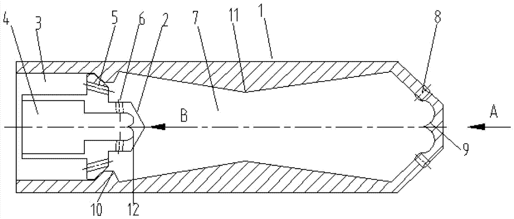
[0018] figure 1 It is a schematic diagram of the structure of a low-resistance internal-mixing air-nucleus atomizing oil gun. figure 1 It can be seen that a low-resistance internal mixing gas core atomizing oil gun includes a Venturi oil gun housing 1 and a mixing core 2 placed inside the V...


PUM


Abstract

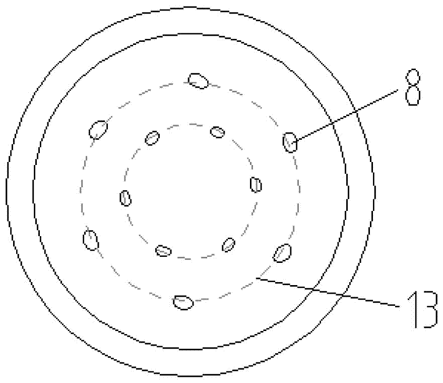
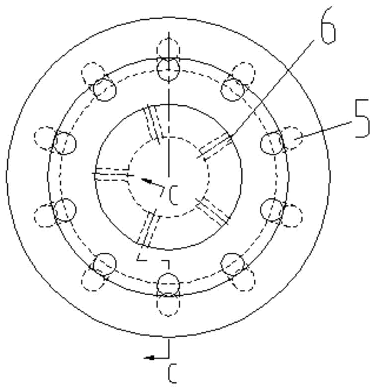
The invention discloses a low-resistance internal mixing type gas nucleus atomization oil gun aims at achieving the technical purposes that oil mist mixing is uniform and combustion is complete, and belongs to the technical field of fuel oil atomization. The atomization oil gun comprises an oil gun shell and a mixing core arranged on the inner side of the tail of the oil gun shell. A fuel oil channel is arranged on the inner side of a center barrel at the tail end of the mixing core. An automation medium channel is arranged between the outer side of the center barrel and the inner side face of the oil gun shell. The front end of the fuel oil channel is provided with a blind hole. The wall of the blind hole is provided with multiple radial oil spraying holes. The inner side face on the top of the blind hole is provided with a first conical flow guide device. Multiple automation medium spraying holes are formed in the outward-convex face of the shoulder of the mixing core and located at the front end of the atomization medium channel. An oil-gas mixing chamber in the middle of an inner cavity of the oil gun shell is of a Venturi structure, the top of the front end of the oil-gas mixing chamber is provided with a second conical flow guide device, and the inclined face of a cone frustum of the front end of the oil gun shell is provided with secondary atomization spraying holes. The low-resistance internal mixing type gas nucleus atomization oil gun has the advantages that the mixing core and the oil-gas mixing chamber are provided with flow guide parts correspondingly, oil mist mixing is uniform and combustion is complete under the rectification effect of a Venturi pipe of the oil-gas mixing chamber, and the low-resistance internal mixing type gas nucleus atomization oil gun is suitable for combusting various kinds of oil.

Description

technical field [0001] The invention relates to a medium atomization oil gun, in particular to an oil gun with high efficiency, small atomization particle size and large output, which adopts medium atomization for combustion in industries and power plants, and belongs to the technical field of fuel atomization. Background technique [0002] Fuel oil has been widely used in all walks of life. The combustion of oil requires the oil gun to atomize the fuel oil into tiny particles and then mix it with the combustion air to burn the fuel oil to the greatest extent. Therefore, the performance of the oil gun affects the fuel oil. Burner ignition, fire, combustion stability, combustion efficiency, pollution emissions, etc. In addition, the particle size of the fuel oil atomized by the oil gun, whether the shape of the sprayed oil mist can match the air, and whether the air can penetrate the oil mist layer are the key to measure the performance of the oil gun. [0003] Medium atomiz...

Claims


Application Information

Patent Timeline
Patent Type & Authority Applications(China)
IPC IPC(8): F23D11/10
CPCF23D11/102
Inventor 陈宝明徐正贾丹丹
Owner SHANGHAI WISEBOND TECH
Why Eureka
Try Eureka