
Manufacturing method of thin film transistor, thin film transistor and display substrate

A technology for thin film transistors and a manufacturing method, which is applied in the fields of transistors, semiconductor/solid-state device manufacturing, semiconductor devices, etc., can solve the problems of affecting the electron mobility of thin-film transistors, unsatisfactory contact between amorphous silicon patterns and polysilicon patterns, etc. Mobility, performance improvement, effect of multi-touch area

Inactive Publication Date: 2017-09-29
BOE TECH GRP CO LTD +1
View PDF8 Cites 4 Cited by
  • Summary
  • Abstract
  • Description
  • Claims
  • Application Information

AI Technical Summary

Problems solved by technology

[0005] The purpose of the present invention is to solve the problem that the contact between the amorphous silicon pattern and the polysilicon pattern in the active layer of the existing thin film transistor is not ideal, which affects the electron mobility of the thin film transistor

Method used


Image

  • Manufacturing method of thin film transistor, thin film transistor and display substrate
  • Manufacturing method of thin film transistor, thin film transistor and display substrate
  • Manufacturing method of thin film transistor, thin film transistor and display substrate

Examples


Embodiment Construction

[0030] In order to make the technical problems, technical solutions and advantages to be solved by the present invention clearer, the following will describe in detail with reference to the drawings and specific embodiments.

[0031] The invention provides a solution to the problem that the electron mobility of the thin film transistor is lowered due to the unsatisfactory contact between the amorphous silicon pattern and the polysilicon pattern in the active layer of the existing thin film transistor.

[0032] On the one hand, an embodiment of the present invention provides a method for manufacturing a thin film transistor, including a step of forming an active layer, the step including:

[0033] Step S1, refer to Figure 2A , sequentially forming a polysilicon layer 22 and a protective layer 23 on the base substrate 21;

[0034] Step S2, refer to Figure 2B , using the first etching gas to etch the protective layer 23 to obtain the protective pattern 23* formed by the prote...


PUM

PropertyMeasurementUnit
Thicknessaaaaaaaaaa

Abstract

The invention provides a manufacturing method of a thin film transistor, the thin film transistor and a display substrate. The manufacturing method comprises the following steps: forming a polycrystalline silicon graph layer and a protective graph layer in sequence on a substrate; using first etching gas to etch the protective graph layer so as to obtain a protective graph; using the protective graph as a mask plate, using second etching gas, and etching the protective graph and the polycrystalline silicon graph layer simultaneously to obtain a polycrystalline silicon graph and a protective residual graph, wherein the rate of the protective graph being etched by the second etching gas is not smaller than that of the polycrystalline silicon graph layer being etched by the second etching gas; forming an amorphous silicon graph, wherein the etching side face of the amorphous silicon graph is in contact with the etching side face of the polycrystalline silicon graph, a part of the protective residual graph is exposed, and the polycrystalline silicon graph and the amorphous silicon graph form an active layer together. Through the scheme in the invention, the polycrystalline silicon graph with a slope can be formed on the etching side face, so that larger contact area of the amorphous silicon graph is obtained, and the electronic mobility of the thin film transistor can be improved.

Description

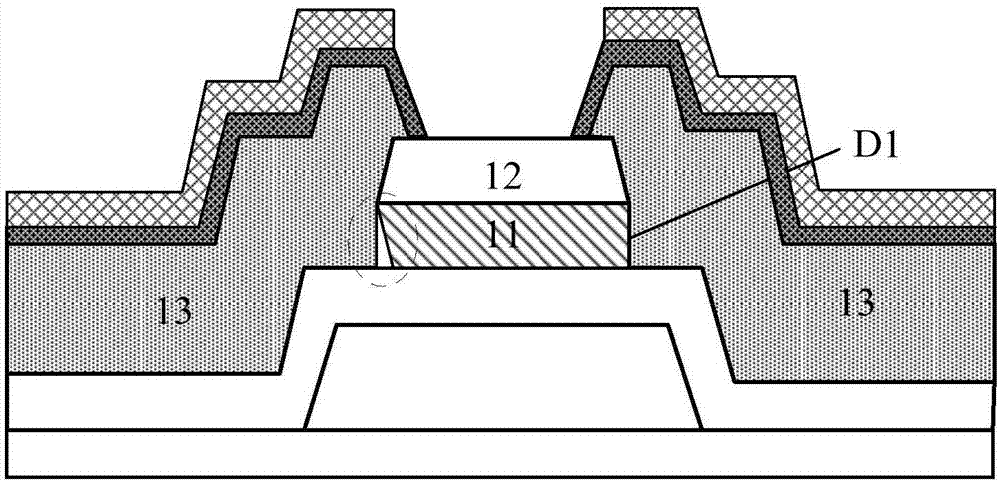
technical field [0001] The invention relates to the field of display, in particular to a manufacturing method of a thin film transistor, a thin film transistor and a display substrate. Background technique [0002] With the development of liquid crystal display technology, the requirements for the electron mobility of the active layer of the thin film transistor are getting higher and higher. The traditional active layer made of amorphous silicon material can no longer meet the performance requirements in terms of electron mobility. (The low electron mobility of the semiconductor layer will lead to the low on-state current of the thin film transistor). The current solution is to use a double-layer structure of polysilicon and amorphous silicon as the active layer, and the polysilicon layer has a sufficiently high electron mobility in an open state to make up for the deficiency of the amorphous silicon layer. [0003] refer to figure 1 As shown, in the existing thin film tr...

Claims


Application Information

Patent Timeline
IPC IPC(8): H01L21/336H01L29/786
CPCH01L29/66757H01L29/78666H01L29/78675H01L29/78696H01L21/31116H01L21/32135H01L21/32139H01L29/66765H01L29/78669H01L21/308H01L21/31144H01L29/78678
Inventor 钱海蛟操彬彬杨成绍黄寅虎
Owner BOE TECH GRP CO LTD
Learn More