
Electronic element grounding structure

A technology of electronic components and grounding structure, which is applied in the field of grounding structure of electronic components, can solve the problems of grounding effect and shielding effect to be improved, limited structure and interference source, and achieve the effect of optimizing contact effect, optimizing grounding, and increasing contact area

Pending Publication Date: 2017-09-29
SHANGHAI TRANSSION CO LTD
View PDF11 Cites 2 Cited by
  • Summary
  • Abstract
  • Description
  • Claims
  • Application Information

AI Technical Summary

Problems solved by technology

[0004] However, this method is limited by the structure and interference sources, and its grounding effect and shielding effect need to be improved

Method used


Image

  • Electronic element grounding structure
  • Electronic element grounding structure
  • Electronic element grounding structure

Examples


Embodiment Construction

[0036] In order to make the purpose, technical solutions and advantages of the embodiments of the present invention clearer, the technical solutions in the embodiments of the present invention will be clearly and completely described below in conjunction with the drawings in the embodiments of the present invention. Obviously, the described embodiments It is a part of embodiments of the present invention, but not all embodiments. Based on the embodiments of the present invention, all other embodiments obtained by persons of ordinary skill in the art without creative efforts fall within the protection scope of the present invention.

[0037] The technical solution of the present invention will be described in detail below with specific embodiments. The following specific embodiments may be combined with each other, and the same or similar concepts or processes may not be repeated in some embodiments.

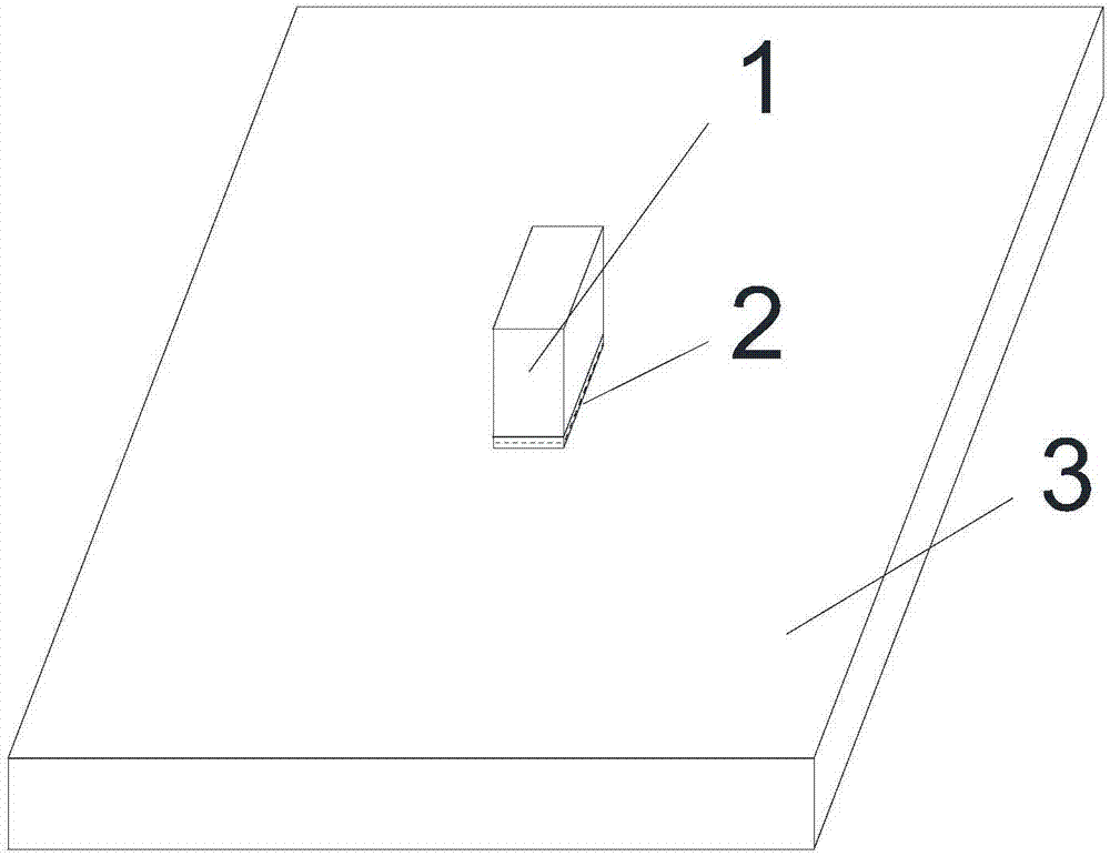
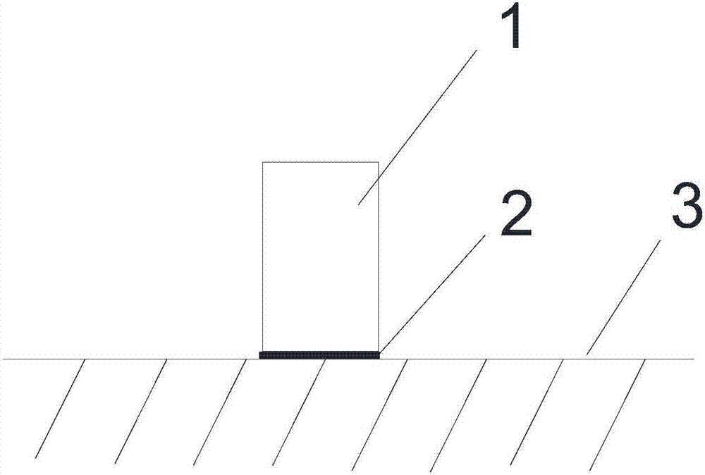
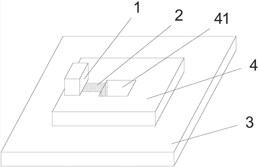
[0038] figure 1 It is a three-dimensional view of the grounding structure ...


PUM


Abstract

The embodiment of the invention relates to the technical field of electronic element assembling, and particularly relates to an electronic element grounding structure. The electronic element grounding structure comprises an electronic element, conductive fabric and a grounding member having a grounding point. The conductive fabric is fiber cloth of which the surface is coated by a conductive metal layer. The conductive fabric is connected with the electronic element and the grounding point, and the electronic element is electrically conducted with the grounding member through the conductive fabric. Compared with the structures in the prior art, the contact effect of the electronic element and the grounding member can be optimized by the electronic element grounding structure so that the grounding and interference shielding effect of the electronic element can be optimized and the radio frequency index can also be enhanced.

Description

technical field [0001] Embodiments of the present invention relate to the technical field of electronic component assembly, and in particular, to a grounding structure for electronic components. Background technique [0002] Since electronic equipment has intermittent or continuous voltage and current changes during operation, rapid voltage changes cause electromagnetic energy to be generated in different frequency bands, that is, electromagnetic interference. With the development of technology, the frequency band of electronic equipment has increased dramatically, and the electromagnetic interference between different electronic components has become more and more serious. [0003] In the prior art, the electronic components are grounded by setting several grounding points on the electronic components and directly contacting these grounding points with the grounding area, so as to solve the problem of electromagnetic interference. [0004] However, this method is limited b...

Claims


Application Information

Patent Timeline
IPC IPC(8): H01R4/64
CPCH01R4/64
Inventor 张丙琳夏雨
Owner SHANGHAI TRANSSION CO LTD
Learn More