
Dissymmetrically-arranged single-piezoelectric stack driving type bidirectional rotary inertia actuator

A two-way rotation, anti-symmetric technology, applied in piezoelectric effect/electrostrictive or magnetostrictive motors, generators/motors, electrical components, etc., can solve low actuation efficiency, clamp failure, small step distance and other problems, to achieve the effect of improving actuation efficiency, improving output performance, and increasing angular displacement output speed

Active Publication Date: 2017-09-29
西安朗威科技有限公司
View PDF6 Cites 3 Cited by
  • Summary
  • Abstract
  • Description
  • Claims
  • Application Information

AI Technical Summary

Problems solved by technology

[0004] Generally, rotary inertial piezoelectric actuators often use bimorphs or multiple piezoelectric stacks as driving elements, which have complex structures and high costs; currently, most rotary inertial actuators only rely on line contacts for clamping , the clamp is likely to fail due to surface wear during the actuation process; in addition, the step distance of a large number of piezoelectric inertial actuators is very small, in order to achieve high-speed corner output, the requirements for the drive system are often high, and the actuation efficiency is low

Method used


Image

  • Dissymmetrically-arranged single-piezoelectric stack driving type bidirectional rotary inertia actuator
  • Dissymmetrically-arranged single-piezoelectric stack driving type bidirectional rotary inertia actuator
  • Dissymmetrically-arranged single-piezoelectric stack driving type bidirectional rotary inertia actuator

Examples


Embodiment Construction

[0020] The present invention will be described in further detail below in conjunction with the accompanying drawings and specific embodiments.

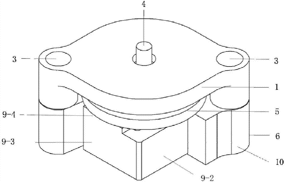
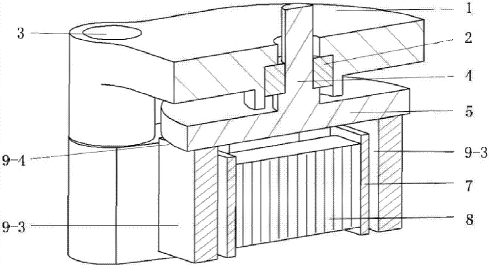
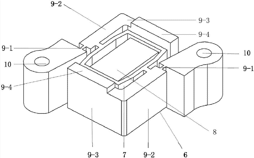
[0021] Such as Figure 1 to Figure 3 As shown, the anti-symmetric arrangement type unimorph stack driven bidirectional rotary inertial actuator of the present invention includes an upper end cover 1, a bearing 2, an output shaft 4, a rotating disk 5 and an actuating mechanism 6; the actuating mechanism 6 For integrated processing, the center of the diamond-shaped ring 7 is anti-symmetrically arranged. The interior of the diamond-shaped ring 7 is interference-fitted with a piezoelectric stack 8 along the axial direction. L-shaped lever magnifying mechanism, one end of the axial rod 9-2 of the L-shaped lever magnifying mechanism is connected with the installation platform 10 through the flexible hinge 9-1, and the other end is fixedly connected with the transverse rod 9-3, and the transverse rod 9-3 There is a friction foot 9-4 protrud...


PUM


Abstract

The invention relates to a dissymmetrically-arranged single-piezoelectric stack driving type bidirectional rotary inertia actuator. The actuator comprises an upper end cover, a bearing, an output shaft, a rotary round disc and an actuating mechanism, wherein the actuating mechanism is integratedly processed and is dissymmetrically arranged about a center of a diamond ring in the actuating mechanism, a piezoelectric stack is in interference fit with the interior of the diamond ring along an axial direction, two side planes of the diamond ring are respectively and rigidly connected with L-shaped lever amplification mechanisms along the axial direction, one end of an axial rod piece of each L-shaped lever amplification mechanism is connected with an installation table by a flexible hinge, the other end of the axial rod piece is fixedly connected with a horizontal rod piece, a friction foot is processed on the horizontal rod piece in a protruding way, the rotary round disc is horizontally arranged above the friction foot of the actuating mechanism, the output shaft is arranged at in disc center of an upper surface of the rotary round disc and is connected with the upper end cover by the bearing, the upper end cover is in a spindle shape, and through holes are formed in two ends of the upper end cover and are tightly connected with the actuating mechanism at a bottom end by bolts. The actuator is small in size and novel in structure, and high-accuracy bidirectional rotation motion can be stably achieved only by driving a single piezoelectric stack.

Description

technical field [0001] The invention belongs to the technical field of inertial piezoelectric actuators, and in particular relates to an antisymmetrically arranged single piezoelectric stack-driven bidirectional rotary inertial actuator and an actuating method. Background technique [0002] Inertial piezoelectric actuator is a kind of mechanism that adopts asymmetrical driving signal, asymmetrical mechanical clamping structure or asymmetrical friction force as the control mode, and forms the driving mechanism through inertial impact motion. [0003] Compared with other types of piezoelectric drives, inertial piezoelectric actuators have the main advantages of simple structure, fast response, high resolution, large stroke, fast movement speed, and low cost. positioning accuracy. Therefore, inertial piezoelectric actuators are suitable for occasions that require high resolution and large strokes. At present, scientific and technological workers have successfully applied iner...

Claims


Application Information

Patent Timeline
Patent Type & Authority Applications(China)
IPC IPC(8): H02N2/14H02N2/12
CPCH02N2/123H02N2/142
Inventor 邵妍徐明龙宋思扬张舒文
Owner 西安朗威科技有限公司
Learn More