Dual control voltage dB linear VGA (Variable Gain Amplifier) circuit with large gain range and high precision

A gain control and voltage control technology, applied in gain control, amplification control, electrical components, etc., can solve the problem of mutual restriction between the gain range and gain error of the variable gain amplifier, and reduce the gain error and increase the gain range. Effect

Inactive Publication Date: 2017-09-29
HARBIN INST OF TECH
View PDF3 Cites 2 Cited by
  • Summary
  • Abstract
  • Description
  • Claims
  • Application Information

AI Technical Summary

Problems solved by technology

[0005] The purpose of the present invention is to solve the mutual constraint problem between the gain range and the gain error of the variable gain amplifier of the existing gain attenuation structure, thereby providing a double control voltage dB linear VGA circuit with a large gain range and high precision

Method used


Image

  • Dual control voltage dB linear VGA (Variable Gain Amplifier) circuit with large gain range and high precision
  • Dual control voltage dB linear VGA (Variable Gain Amplifier) circuit with large gain range and high precision
  • Dual control voltage dB linear VGA (Variable Gain Amplifier) circuit with large gain range and high precision

Examples


specific Embodiment approach 1

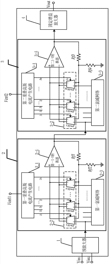
[0024] Specific implementation mode one: combine figure 1 Describe this embodiment in detail. The dual control voltage dB linear VGA circuit with large gain range and high precision described in this embodiment includes a pre-amplifier 1, a large-range gain control stage 2, a high-precision gain control stage 3, and a fixed gain amplifier. 4;

[0025] The pre-amplifier 1 has two input terminals Vin1 and Vin2 respectively, the output terminal of the pre-amplifier 1 is connected to the signal input terminal of the wide-range gain control stage 2, and the output terminal of the wide-range gain control stage 2 is connected to the signal input terminal of the high-precision gain control stage 3. The signal input terminal is connected, the output terminal of the high-precision gain control stage 3 is connected with the input terminal of the fixed gain amplifier 3, the first control voltage Vctrl1 is input from the control voltage input terminal of the wide-range gain control stage 2...

specific Embodiment approach 2

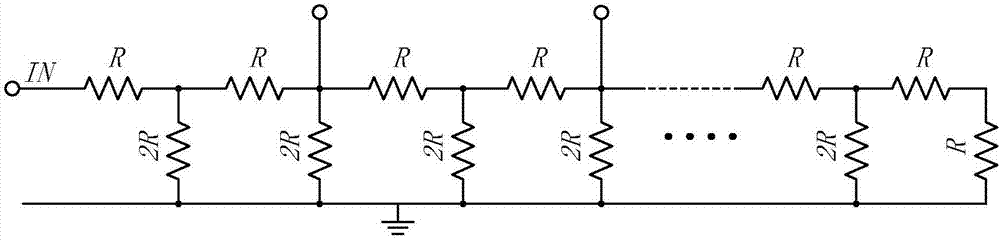
[0032] Specific implementation mode two: combination figure 2 Describe this embodiment in detail. This embodiment is a further description of the first specific embodiment. In this embodiment, the first attenuation network 2-3 is realized by an R-2R ladder resistor array, and the large-range gain control stage 2 has a gain reduction step size of 12dB.

[0033] The R-2R ladder resistor array includes 2N resistors with a resistance of R and 2N-1 resistors with a resistance of 2R. The 2N resistors with a resistance of R are connected in series to form 2N+1 endpoints, and the first endpoint is also used as The signal input terminal of the large-range gain control stage 2 and 1 output terminal of the first attenuation network 2-3, the 3rd, 5, ..., 2N-1 terminals are used as the N of the first attenuation network 2-3 -1 output terminal, 2N+1 terminals are grounded, the 2nd to 2N-1 terminals are respectively connected to one end of 2N-1 resistors with a resistance value of 2R, and ...

specific Embodiment approach 3

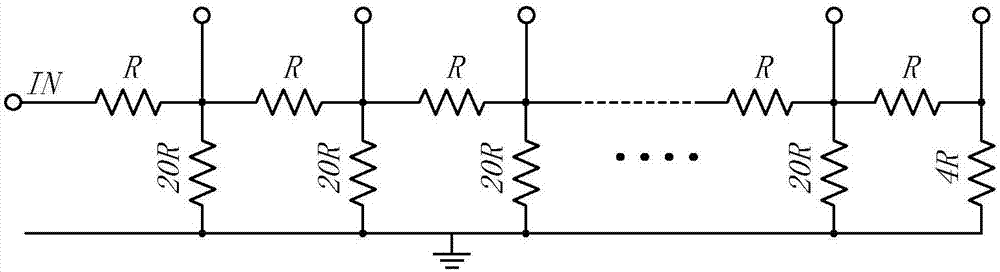
[0034] Specific implementation mode three: combination Figures 3 to 5 This embodiment is described in detail. This embodiment is a further description of the first embodiment. In this embodiment, preferably, the second attenuation network 3-3 is realized by a resistor network of R-4R-20R. Select the output node so that the gain attenuation step size of the high-precision gain control stage 3 is 2dB;

[0035] The resistor network of R-4R-20R includes M-1 resistors with a resistance of R, 1 resistor with a resistance of 4R and M-2 resistors with a resistance of 20R;

[0036] M-1 resistors with a resistance value of R are connected in series to form M endpoints, the first endpoint is simultaneously used as the signal input end of the high-precision gain control stage 3 and an output end of the second attenuation network 3-3, the second to the second The M-1 terminals are respectively connected to one end of M-2 resistors with a resistance value of 20R, and are used as the M-2 o...


PUM


Abstract

Disclosed is a dual control voltage dB linear VGA (Variable Gain Amplifier) circuit with large gain range and high precision, relating to a gain control level circuit, and solving the problem that the gain range and gain error of the existing gain reduction structured variable gain amplifier restrict each other. The output end of a preamplifier is connected with the signal input end of a large range gain control level, the output end of the large range gain control level is connected with the signal input end of a high precision gain control level, the output end of the high precision gain control level is connected with the input end of a fixed gain amplifier, the first control voltage Vctrl1 is input by the control voltage input end of the large range gain control level, and the second control voltage Vctrl2 is input by the control voltage input end of the high precision gain control level. The circuit is suitable for amplifying or reducing signals.

Description

technical field [0001] The invention relates to a gain control stage circuit, in particular to a double control voltage dB linear VGA circuit with large gain range and high precision based on a gain attenuation structure. Background technique [0002] Analog circuits need to amplify or attenuate the signal, which is accomplished by a variable gain amplifier. As an indispensable module of the analog RF front end, the variable gain amplifier is widely used in many aspects such as disk reading drive circuits, magnetic data storage systems, electromagnetic meters, and TV tuners. In communication systems such as optical fiber communication, microwave communication, and satellite communication, as well as radar and broadcast television systems, in order to realize that the establishment time of the automatic gain control loop has nothing to do with the amplitude of the input signal, the variable gain amplifier in the loop must have a dB linear gain control features. With the vig...

Claims


Application Information

Patent Timeline
Patent Type & Authority Applications(China)
IPC IPC(8): H03G3/30
CPCH03G3/3036
Inventor 王永生李心智付方发来逢昌
Owner HARBIN INST OF TECH
Why Eureka
Try Eureka