
Eye ground hyperspectral imaging device

A technology of hyperspectral imaging and imaging unit, applied in the field of optical imaging, can solve problems such as poor reliability, inability to realize wide-band spectral band conversion, etc., and achieve the effects of simple structure, good clinical application prospects, and wide spectral range.

Active Publication Date: 2017-10-03
XI'AN INST OF OPTICS & FINE MECHANICS - CHINESE ACAD OF SCI
View PDF6 Cites 3 Cited by
  • Summary
  • Abstract
  • Description
  • Claims
  • Application Information

AI Technical Summary

Problems solved by technology

[0004] The purpose of the present invention is to provide a fundus hyperspectral imaging device to overcome the defects in the prior art that cannot realize spectral band conversion in a wide-band continuous wavelength range and have poor reliability

Method used


Image

  • Eye ground hyperspectral imaging device
  • Eye ground hyperspectral imaging device

Examples


Embodiment Construction

[0015] The present invention will be described in detail below in conjunction with specific embodiments and accompanying drawings.

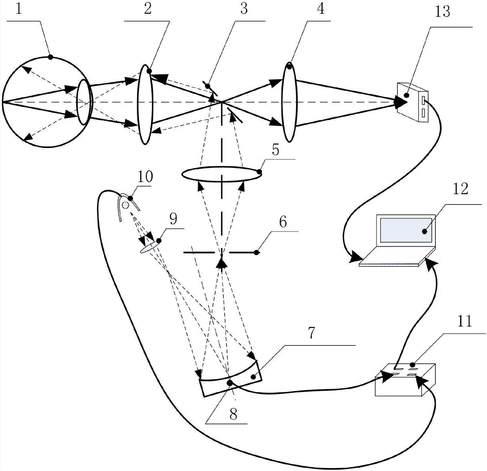
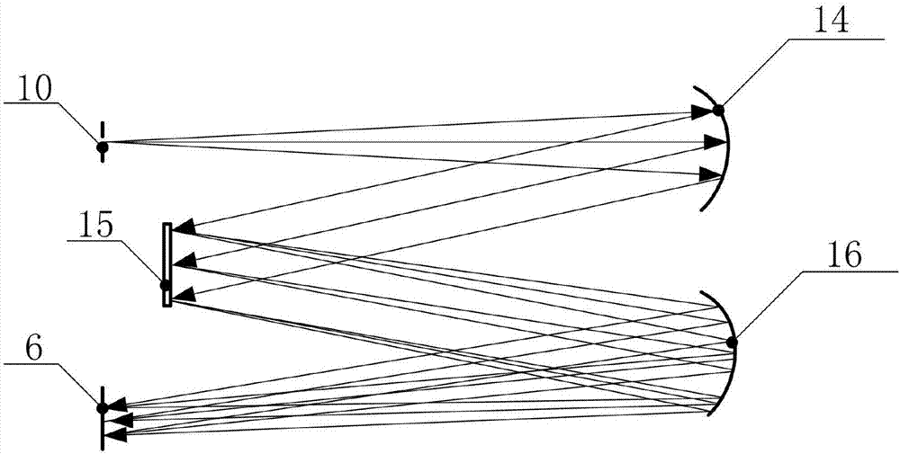
[0016] Such as figure 1 As shown, Embodiment 1 provides a fundus hyperspectral imaging device, including an illumination unit, an imaging unit, and a control unit. The illumination unit includes a light source 10, and a first condenser lens that is disposed between the light source 10 and the fundus along the propagation direction of the optical path in sequence. 9. Adjustable concave diffraction grating 7, diaphragm 6, second condenser lens 5, hollow mirror 3 and omentum objective lens 2, said imaging unit includes area array detector 13 and control computer 12, and is arranged on the fundus and said The omentum objective lens 2 , the hollow mirror 3 and the imaging mirror 4 are sequentially arranged between the area array detectors 13 along the propagation direction of the optical path, and the control computer 12 is connected to the area array...


PUM


Abstract

The invention relates to the technical field of optical images, in particular to an eye-ground hyperspectral imaging device. The eye-ground hyperspectral imaging device is used for overcoming the problems that in the prior art, spectral transformation in a broad-band continuous wavelength range cannot be achieved and the reliability is poor. The eye-ground hyperspectral imaging device includes a lighting unit, an imaging unit and a controlling unit. The lighting unit includes a light source, a first converging lens, an adjustable concave diffraction grating, a diaphragm, a second collecting lens, a medium altitude reflector and a retinal objective, wherein the first converging lens, the adjustable concave diffraction grating, the diaphragm, the second collecting lens, the medium altitude reflector and the retinal objective are sequentially arranged between the light source and the eye ground in the direction of light path transmission. The imaging unit includes an area-array detector and a controlling computer, a retinal objective, a hollow reflector and an imaging mirror, wherein the retinal objective, the hollow reflector and the imaging mirror are successively arranged between the eye ground and the area-array detector in the direction of the light path transmission; the controlling computer is connected to the area-array detector. The controlling unit includes a controller, a rotating shaft is arranged on the adjustable concave diffraction grating, and the controller is connected to the controlling computer, the light source and the rotating shaft of the adjustable concave diffraction grating separately.

Description

technical field [0001] The invention belongs to the technical field of optical imaging, and in particular relates to a fundus hyperspectral imaging device. Background technique [0002] Fundus imaging technology has become an important method of ophthalmic disease detection, and this technology has become standard practice for observing, interpreting, diagnosing, and documenting retinal health and disease. Retinal vascular abnormalities represent systemic microvascular disease to a certain extent, and are the pathological basis of target organ damage in metabolic syndrome. The retinal microcirculation system is very similar to the blood circulation system of the heart, brain, kidney and other organs in terms of structure and function, and can objectively reflect the development and changes of systemic diseases. Many people have developed corresponding fundus diseases before clinical symptoms appear. Abnormal manifestations also indicate that some fundus abnormalities can ap...

Claims


Application Information

Patent Timeline
IPC IPC(8): A61B3/14A61B3/12
CPCA61B3/12A61B3/14Y02A40/10
Inventor 胡炳樑张周锋李思远张兆会于涛刘永正卫翠玉许黄蓉
Owner XI'AN INST OF OPTICS & FINE MECHANICS - CHINESE ACAD OF SCI
Learn More