
Mineral-powder rapid reducing system

A fast, mineral powder technology, applied in the field of metallurgy, can solve the problems of easy bonding of fine-grained mineral powder, carbon precipitation hindering normal operation, low reduction speed, etc., to improve metallization rate, enhance reduction effect, reduce The effect of the risk of oxidation

Pending Publication Date: 2017-10-03
SHENWU TECH GRP CO LTD
View PDF0 Cites 5 Cited by
  • Summary
  • Abstract
  • Description
  • Claims
  • Application Information

AI Technical Summary

Problems solved by technology

The disadvantage is that the fine-grained ore powder is very easy to bond. Generally, it is operated at a low temperature of 600-700 ° C. Not only the reduction speed is not high, but also it is easy to promote the carbon precipitation reaction of CO, and carbon precipitation hinders normal operation.

Method used


Image

  • Mineral-powder rapid reducing system
  • Mineral-powder rapid reducing system
  • Mineral-powder rapid reducing system

Examples


Embodiment 1

[0061] This embodiment includes the following structures:

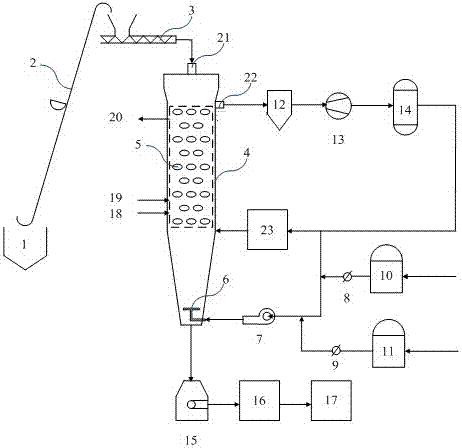
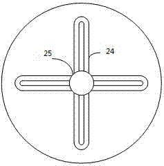
[0062] Rapid reduction reactor: The rapid reduction reactor 4 has a circular cross section and can be divided into a feed section, a reduction section and a cooling section. The need for pressurization within the unit. Wherein, the feed section is located at the top of the reactor 4; the reduction section is located between the feed section and the cooling section, and its inside is arranged in multiple layers along the height direction of the fast reduction reactor. The thermal storage radiant tubes 5 parallel to each other in the horizontal direction have a conical cooling section and are located at the bottom of the reactor 4, which facilitates the powdery material to slide down to the product outlet and avoid local accumulation of the product; a cloth is arranged inside the cooling section of the reactor 4 The wind plate 6 allows the reducing gas to uniformly enter the reactor and undergo a reduction reaction wit...

Embodiment 2

[0072] Rapid reduction reactor: The rapid reduction reactor 4 has a circular cross section and can be divided into a feed section, a reduction section and a cooling section. The need for pressurization within the unit. Wherein, the feed section is located at the top of the reactor 4; the reduction section is located between the feed section and the cooling section, and its inside is arranged in multiple layers along the height direction of the fast reduction reactor. The thermal storage radiant tubes 5 parallel to each other in the horizontal direction have a conical cooling section and are located at the bottom of the reactor 4, which facilitates the powdery material to slide down to the product outlet and avoid local accumulation of the product; a cloth is arranged inside the cooling section of the reactor 4 The wind plate 6 allows the reducing gas to uniformly enter the reactor and undergo a reduction reaction with the ore powder. In addition, the side wall at the top of t...


PUM

PropertyMeasurementUnit
particle diameteraaaaaaaaaa

Abstract

The invention relates to a rapid reduction system for producing direct reduced iron from powdery ore, comprising: a rapid reduction reactor, a heating system, a feed system, a discharge system, and a reduction gas system, the temperature distribution in the device is uniform, and the reduction tail gas circulation is adopted The method of utilization realizes the recycling of reducing gas resources, adopts multi-layer air inlets, the distribution of reducing gas is more uniform, and the hot reducing gas entering the reactor can directly continue to undergo reduction reaction with unreacted ore powder, which is beneficial Improve the metallization rate in the reduction product and enhance the reduction effect.

Description

technical field [0001] The invention belongs to the technical field of metallurgy, in particular to a mineral powder reduction system, in particular to a mineral powder rapid reduction system. Background technique [0002] Direct reduction ironmaking technology is the cutting-edge technology for the development of the iron and steel industry. 2 It is an important development direction to reduce emissions, improve the structure of iron and steel products, and improve the quality of iron and steel products. Direct reduced iron is a substitute for high-quality steel scrap, an indispensable iron source raw material for the production of high-quality pure steel, and a high-quality coolant for converter steelmaking. [0003] The direct reduction methods that have reached the industrial production level or are still being tested are mainly divided into two categories: the direct reduction method using a gas reducing agent and the direct reduction method using a solid reducing agen...

Claims


Application Information

Patent Timeline
Patent Type & Authority Applications(China)
IPC IPC(8): C21B13/04
CPCC21B13/04C21B13/0073
Inventor 郑倩倩王培伦彭丽田广胜孟嘉乐窦从从吴道洪
Owner SHENWU TECH GRP CO LTD
Learn More