An electric egr valve anti-carbon sticking mechanism
An EGR valve and anti-carbon technology, which is applied in the direction of engine components, machines/engines, mechanical equipment, etc., can solve the problems of valve discs that cannot be opened, EGR valve failure, etc., and achieve the effect of avoiding inability to open
- Summary
- Abstract
- Description
- Claims
- Application Information
AI Technical Summary
Problems solved by technology
Method used
Image

Examples
Embodiment 1
[0017] This embodiment is a method for preventing sticking of carbon deposits in an electric EGR valve. The method is as follows: when the engine is turned off, the valve disc of the electric EGR valve is prevented from contacting the valve seat to avoid sticking after the valve disc and the valve seat are cooled. lag.
[0018] The idea of this embodiment is to separate the valve seat and disc of the electric EGR valve when the engine is stopped, so that the two cannot stick. In practice, most of the actual situations are that the valve seat and the valve disc are separated, but there are situations where the valve disc and the valve seat are together, that is, the valve seat and the valve disc are closed. As long as the seat and disc are closed, the problem of seat and disc sticking will occur. Therefore, this embodiment adopts a very simple and effective method: when the engine is stopped, the valve disc and the valve seat are separated, the most basic conditions of the t...
Embodiment 2
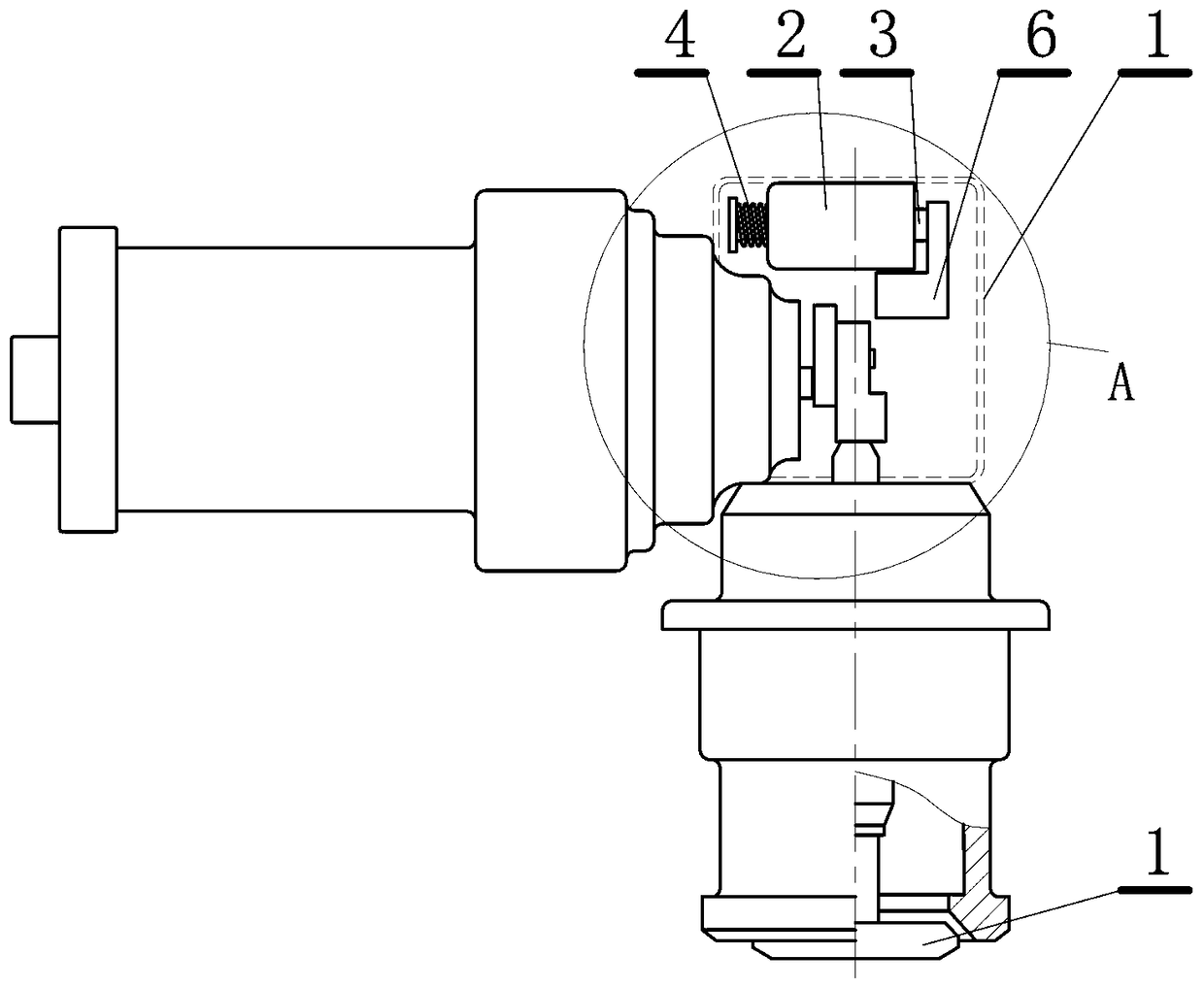
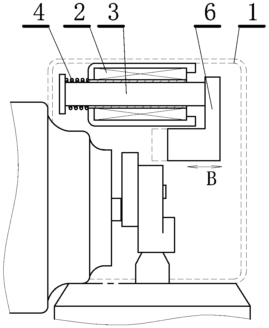
[0022] This embodiment is an improvement of the first embodiment, which is a refinement of the first embodiment on the way of preventing the valve flap from contacting the valve seat. In this embodiment, when the engine is turned off, the way to prevent the valve disc from contacting the valve seat is to set an electric blocking block to prevent the reciprocating mechanism driven by the electric motor of the electric EGR valve from reaching the closed position of the valve disc and the valve seat when the engine is turned off. .
[0023] This embodiment adopts a simple electromechanical structure. When the engine is turned off, a blocking block is inserted into the reciprocating mechanism of the EGR valve to block the movement of the reciprocating mechanism to achieve the effect of preventing the valve seat and the valve disc from closing. Of course, the EGR motor should also have a protection device, which can stop the rotation when it is blocked, so as to prevent the motor c...
Embodiment 3
[0025] This embodiment is an improvement of the first embodiment, which is a refinement of the first embodiment on the way of preventing the valve flap from contacting the valve seat. In this embodiment, when the engine is turned off, the way to prevent the valve disc from contacting the valve seat is to set an electric blocking block inserted between the valve disc and the valve seat to prevent the valve disc and the valve seat from closing.
[0026] This embodiment also adopts the way of the blocking block, but the blocking position of the blocking block is different from that of the second embodiment. In this embodiment, the blocking block is arranged between the valve seat and the valve flap to directly block the closing of the two.
PUM
 Abstract
Description
Claims
Application Information
 - R&D
- Intellectual Property
- Life Sciences
- Materials
- Tech Scout
- Unparalleled Data Quality
- Higher Quality Content
- 60% Fewer Hallucinations
Browse by: Latest US Patents, China's latest patents, Technical Efficacy Thesaurus, Application Domain, Technology Topic, Popular Technical Reports.
© 2025 PatSnap. All rights reserved.Legal|Privacy policy|Modern Slavery Act Transparency Statement|Sitemap|About US| Contact US: help@patsnap.com