Multi-impellor rotary vane type hydrodynamic cavitation generator and hydrodynamic cavitation method

A hydraulic cavitation and generating device technology, which is applied in the direction of mechanical oscillation water/sewage treatment, components of pumping devices for elastic fluids, non-variable pumps, etc., can solve the problem that is not enough to trigger physical and chemical reactions or Intensify the effect, deal with problems such as the large pipeline structure of the system, and the small hydraulic cavitation intensity, so as to achieve the effect of low equipment manufacturing cost, reduced scale and complexity, and reduced floor space

Pending Publication Date: 2017-10-03
RES INST OF PHYSICAL & CHEM ENG OF NUCLEAR IND
View PDF7 Cites 14 Cited by
  • Summary
  • Abstract
  • Description
  • Claims
  • Application Information

AI Technical Summary

Problems solved by technology

[0006] Although the research on hydrodynamic cavitation has gradually deepened, and the number of cavitator structures proposed has increased, the cavitation intensity and efficiency of hydrodynamic cavitation are relatively low, which is often not enough to trigger or intensify certain physical and chemical reactions.
In addition, the processing capacity of the cavitation reactor is small, and multiple devices need to be used in parallel or in series for large-scale processing, resulting in a large and complex pipeline structure of the processing system, which is still difficult to promote and apply industrially

Method used


Image

  • Multi-impellor rotary vane type hydrodynamic cavitation generator and hydrodynamic cavitation method
  • Multi-impellor rotary vane type hydrodynamic cavitation generator and hydrodynamic cavitation method
  • Multi-impellor rotary vane type hydrodynamic cavitation generator and hydrodynamic cavitation method

Examples


Embodiment Construction

[0042] The present invention will be described in further detail below in conjunction with the accompanying drawings and specific embodiments. It should be understood that the specific embodiments described here are only used to explain the present invention, not to limit the present invention.

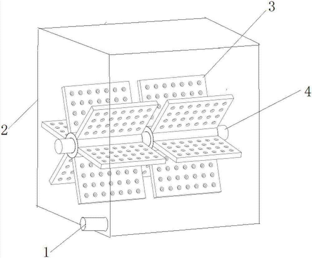
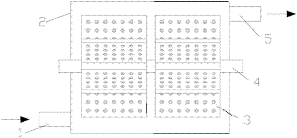
[0043] A multi-impeller rotary blade type hydraulic cavitation generating device, comprising:

[0044] The box body 2 is used to accommodate the liquid. The bottom end of the front side is provided with a liquid inlet 1, and the top end of the rear side is provided with a liquid outlet 5. The liquid inlet 1 and the liquid outlet 5 are respectively arranged at both ends of the diagonal line of the box body;

[0045] Cavitation bodies, including,

[0046] The rotating shaft 4 is installed in the center of the box body 2 and driven by an external motor;

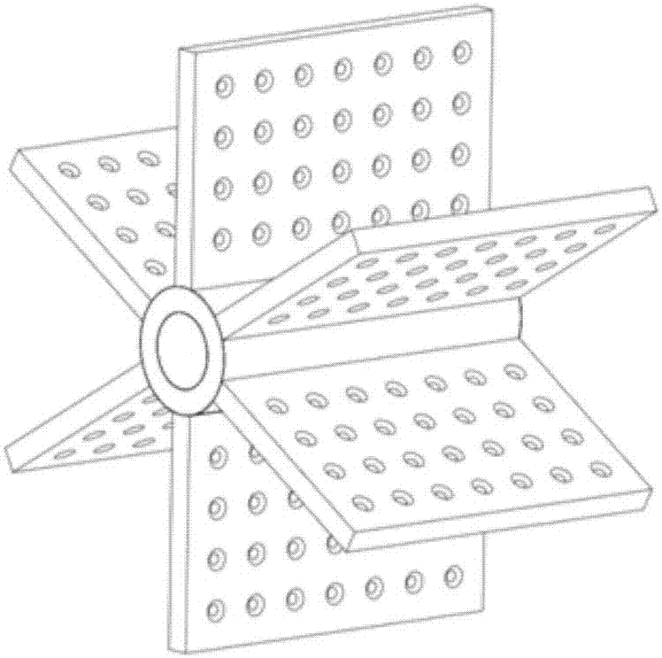
[0047] A plurality of impellers 3 are all coaxially installed on the rotating shaft 4, and each is composed of a plurality of blades...


PUM


Abstract

The invention discloses a multi-impellor rotary vane type hydrodynamic cavitation generator and a hydrodynamic cavitation method. The multi-impellor rotary vane type hydrodynamic cavitation generator comprises a box body and a cavitation mechanism. The box body is used for containing liquid, the bottom end of the front side of the box body is provided with a liquid inlet, and the top end of the back side of the box body is provided with a liquid outlet. The liquid inlet and the liquid outlet are correspondingly arranged at the two ends of the diagonal of the box body. The cavitation mechanism comprises a rotating shaft and a plurality of impellors. The rotating shaft is installed in the center of the interior of the box body and driven by an outer-arranged motor. The impellors are coaxially installed on the rotating shaft, and each impellor is composed of a plurality of vanes. The vanes are provided with penetrating through holes. The multi-impellor rotary vane type hydrodynamic cavitation generator has the advantages of being low in energy consumption, high in cavitation efficiency and the like.

Description

technical field [0001] The invention relates to the technical field of chemical fluids, in particular to a multi-impeller rotary blade type hydraulic cavitation generating device and a hydraulic cavitation method. Background technique [0002] Cavitation refers to the process of the formation, development and collapse of gas cavities inside the liquid or on the liquid-solid interface when the local pressure in the liquid drops. When the liquid pressure drops to even below the saturated vapor pressure of the liquid, a large number of cavitation bubbles are generated due to the violent vaporization of the liquid. Cavitation bubbles expand and grow with liquid flow. When the liquid pressure recovers, the cavitation bubbles collapse instantly to form micro jets and shock waves, resulting in instantaneous local high temperature (1000-5000K) and instantaneous high pressure (1-5×10⁷Pa). Cavitation can lead to performance degradation of hydraulic mechanical equipment, causing vibr...

Claims


Application Information

Patent Timeline
Patent Type & Authority Applications(China)
IPC IPC(8): F04D29/18C02F1/34
CPCF04D29/181F04D29/185C02F1/34
Inventor 魏世超张凯
Owner RES INST OF PHYSICAL & CHEM ENG OF NUCLEAR IND
Why Eureka
Try Eureka